Super-resolution optical recording medium and method for recording information on super-resolution optical recording medium

Inactive Publication Date: 2007-06-21
TDK CORPARATION
View PDF2 Cites 9 Cited by
  • Summary
  • Abstract
  • Description
  • Claims
  • Application Information

AI Technical Summary

Benefits of technology

[0008] In view of the foregoing problems, various exemplary embodiments of this invention provide a super-resolution optical recording medium which can further increase its recording density, and provide a method for recording information on the super-resolution optical recording medium.
[0009] As a result of diligent study, the inventor found that in the surface shape of a super-resolution optical recording medium along a track, forming at least a mark with the size of the resolution limit or less in the modulation code into a concave section with respect to a not-recorded section makes it possible to record information at a high CNR (carrier to noise ratio).
[0015] According to this invention, along the track in the cross section of the super-resolution optical recording medium, at least the short recording mark with the size of the resolution limit or less in the modulation code is formed into the concave section and spaces before and after the recording mark which are in the size of the resolution limit or less are formed into convex sections, so that it is possible to record information at high CNR. Also, it is possible to record information with a preferable frequency characteristic by making the height of the short recording mark with respect to a not-recorded section higher than the height of a long recording mark with respect to the not-recorded section.

Problems solved by technology

Thus, reducing the wavelength λ and / or increasing the numerical aperture NA reduces the resolution limit, and hence increases the recording density.
However, the ability to further shorten the wavelength and increase the numerical aperture is becoming limited.

Method used


Image

  • Super-resolution optical recording medium and method for recording information on super-resolution optical recording medium
  • Super-resolution optical recording medium and method for recording information on super-resolution optical recording medium
  • Super-resolution optical recording medium and method for recording information on super-resolution optical recording medium

Examples


first exemplary embodiment

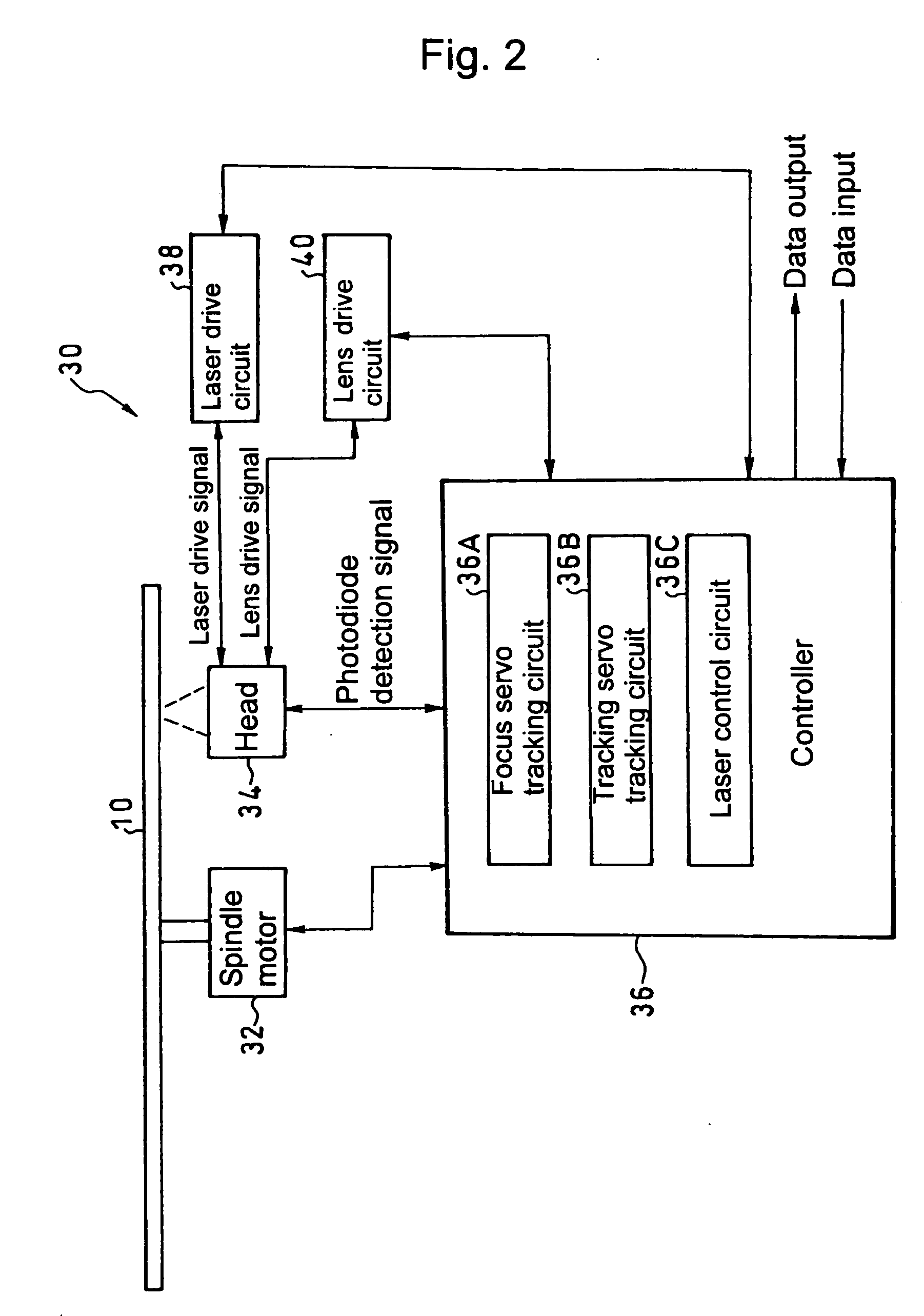
[0026] A first exemplary embodiment of the present invention will be hereinafter described in detail with reference to FIGS. 1 to 3.

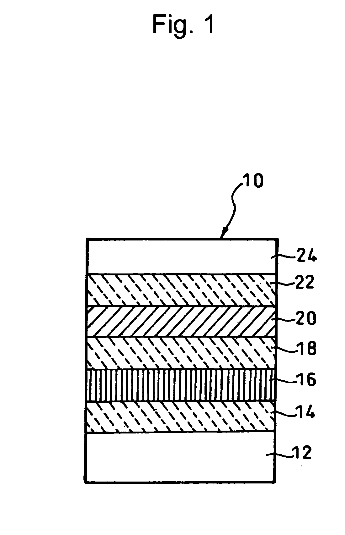
[0027] As shown in FIG. 1, a super-resolution optical recording medium 10 according to the first exemplary embodiment of the present invention is configured to include a first dielectric layer 14, a super resolution layer 16, a second dielectric layer 18, a recording layer 20, a third dielectric layer 22, and a light transmission layer 24, all of which are formed in this order on the substrate 12.

[0028] In the example shown in FIG. 1, a laser beam is incident on the light transmission layer 24 opposite to the substrate 12. When the laser beam is incident on the substrate, however, the substrate serves as a light transmission layer.

[0029] The substrate 12 is made of polycarbonate, for example. The first dielectric layer 14, the second dielectric layer 18, and the third dielectric layer 22 are made of a semiconductor, an oxide or a sulfide of metal or ...

example 1

[0044] A super-resolution optical recording medium according to example 1 includes an Ag-alloy reflection film with a thickness of 40 nm, a first dielectric layer made of ZnS:SiO2=85:15 with a thickness of 80 nm, a super resolution layer made of Sb75Te25 with a thickness of 10 nm, a second dielectric layer made of ZnS:SiO2=85:15 with a thickness of 40 nm, a recording layer made of PtOx with a thickness of 4 nm, a third dielectric layer made of ZnS:SiO2=85:15 with a thickness of 90 nm, and a light transmission layer with a thickness of 0.1 mm, all of which are laminated in this order on a polycarbonate substrate.

[0045] In the medium having such a structure, it is conceivable that recording decomposes the PtOx (the recording layer) into Pt and O2 to deform the recording layer into recording marks, and the optical change of Sb75Te25 (the super resolution layer) makes the reproduction of a signal with the recording marks with the size of the resolution limit or less and spaces with the...

example 2

[0058] A super-resolution optical recording medium according to example 2 includes an Ag-alloy reflection film with a thickness of 40 nm, a first dielectric layer made of ZnS:SiO2=85:15 with a thickness of 80 nm, a super resolution layer made of Sn58Sb42 with a thickness of 15 nm, a second dielectric layer made of ZnS:SiO2=85:15 with a thickness of 45 nm, a recording layer made of PtOx with a thickness of 4 nm, a third dielectric layer made of ZnS:SiO2=85:15 with a thickness of 45 nm, and a light transmission layer with a thickness of 0.1 mm, all of which are laminated in this order on a PC substrate. When recording marks with the size of the resolution limit or less and spaces with the size of the resolution limit or less were successively formed with varying recording power in stages as in the case of the aforementioned example 1, table 5 shows the results of observation as in the case of table 1.

TABLE 5ML = 75 nmh(nm)CNR(dB)Pw(mW)hm / ML−1535.610−0.20−1436.79−0.18−15388−0.20−1240...


PUM


Abstract

A super-resolution optical recording medium has at least a recording layer and a super resolution layer on a substrate. A recording mark with the size of a resolution limit or less and a space with the size of the resolution limit or less are formed in the super-resolution optical recording medium by adjusting the intensity of a laser for recording or an emission pattern of the laser for recording such that at least the recoding mark with the size of the resolution limit or less out of recording marks in a modulation code is formed into a concave section with respect to a not-recorded section.

Description

BACKGROUND OF THE INVENTION [0001] 1. Field of the Invention [0002] The present invention relates to a super-resolution optical recording medium which can reproduce information by irradiating reproduction light onto recording marks formed in a recording layer. The present invention relates in particular to a super-resolution optical recording medium from which small recording marks with the size of the resolution limit or less of the reproduction optical system can be reproduced, and a method for recording information on the super-resolution optical recording medium. [0003] 2. Description of the Related Art [0004] In recent years, as described in, for example, Japanese Patent Laid-Open Publication No. 2003-6872, a super-resolution optical recording medium has been proposed, from which a recording mark train smaller than the diffraction limit of a reproduction optical system can be reproduced. [0005] In the case of a conventional optical recording medium, in general, it is impossible...

Claims


Application Information

Patent Timeline
IPC IPC(8): G11B7/0045
CPCG11B7/0045G11B7/126G11B7/24085G11B7/007G11B7/1263
Inventor FUKUZAWA, NARUTOSHIKIKUKAWA, TAKASHIKOBAYASHI, TATSUHIRO
Owner TDK CORPARATION
Why Eureka
Try Eureka