Method for producing electrophotographic photoreceptor, electrophotographic photoreceptor and image forming apparatus

a photoreceptor and photoreceptor technology, applied in the direction of instruments, nuclear engineering, corona discharge, etc., can solve the problems of high production cost, poor plasticity of the surface, difficult formation of the photosensitive layer, etc., and achieve good photosensitivity and photoresponsiveness, the effect of not reducing the photosensitivity and photoresponsiveness

Inactive Publication Date: 2007-06-21
SHARP KK
View PDF10 Cites 4 Cited by
  • Summary
  • Abstract
  • Description
  • Claims
  • Application Information

AI Technical Summary

Benefits of technology

[0057] According to the invention, an image forming apparatus comprises the electrophotographic photoreceptor mentioned above, a charging unit for charging the electrophotographic photoreceptor, an exposure unit for exposing the charged electrophotographic photoreceptor to light to thereby form an electrostatic latent image thereon, a developing unit for developing the electrostatic latent image formed on the electrophotographic photoreceptor, with a developer containing a toner to thereby form a toner image, and a transfer unit for transferring the toner image onto a recording medium to thereby form an image on the recording medium. In the image forming apparatus of the type, the electrophotographic photoreceptor has good photosensitivity and photo-responsiveness, and even when repeatedly used, its photosensitivity and photo-responsiveness does not lower, and therefore, using the apparatus, it is possible to form good images with no image failures of white skipping and black stripes over a prolonged period of time.

Problems solved by technology

The inorganic photoreceptor may have such basic properties of photoreceptor, but has some drawbacks in that its photosensitive layer is difficult to form, its surface is poorly plastic and is readily scratched, and its production costs are high.
In addition, the inorganic photoconductive substance mentioned above is highly toxic and is seriously limited in point of its production and use.
Though the organic photoreceptor has one problem in that its durability is somewhat poorer than that of the inorganic photoreceptor, it is the mainstream of electrophotographic photoreceptors as having the above-mentioned various advantages.
These organic photoreceptors may satisfy various requirements in a broad range, but have some problems common to them in that the characteristic stability of organic photoreceptors is insufficient.
As a result, an image forming apparatus that comprises such an organic photoreceptor may have some problems of resolution reduction and image failure of white skipping or dark stripes.
The fatigue degradation of a photoreceptor to worsen its characteristic stability may be caused by a charger used as a charging unit for charging the photoreceptor.
Providing an exhaust unit inside an image forming apparatus in that manner may make it possible to exhaust the oxidizing gas around the corona-discharge charger and to prevent the oxidation of the photoconductive substance, but this is problematic in that the constitution of the image forming apparatus may be complicated.
However, a photosensitive layer capable of exhibiting a sufficient gas-barrier property not detracting from the electric properties of the photoconductive substance in the photosensitive layer has not as yet been realized.
However, when the antioxidant is added to the photosensitive layer in such a degree that the oxidation of the photoconductive substance can be thereby prevented, then there may occur some problems in that the photosensitivity of the photoreceptor is lowered or the photo-responsiveness thereof is lowered owing to the change in the sensitive wavelength range, and while the photoreceptor is used repeatedly in an electrophotographic process comprising a series of charging, exposure and discharging, its charge potential may lower and its residual potential may increase.
In order to evade these problems, when the amount of the antioxidant to be added is reduced, then the oxidation of the photoconductive substance could not be sufficiently prevented.
To that effect, the prior-art techniques could not realize a photoreceptor capable of satisfying both good electric properties and good resistance to oxidizing gas.
The process of producing such a contact member is complicated, and, depending on the contact pressure between the contact member and a photoreceptor, a sufficient amount of a hindered amine compound enough for the intended oxidizing gas resistance could not be supplied to the surface of the photoreceptor.
When the contact pressure between the contact member and the photoreceptor is increased in order that a sufficient amount of a hindered amine compound could be supplied to the surface of the photoreceptor, then the photosensitive layer, or that is, the surface layer of the photoreceptor may be worn by the contact pressure and the thickness of the photosensitive layer may be thereby reduced, and there may occur other problems in that the electric properties of the layer may be worsened and the life of the photoreceptor may be shortened.
Accordingly, increasing the types of the coating liquids results in other various problems in that the control of the coating liquids is complicated, the plant investment for viscosity control increases, and the production costs increase in point of the material such as the solvent to be used for the viscosity control since a fresh solvent must be replenished for compensating the solvent that may reduce through vaporization.

Method used


Image

  • Method for producing electrophotographic photoreceptor, electrophotographic photoreceptor and image forming apparatus
  • Method for producing electrophotographic photoreceptor, electrophotographic photoreceptor and image forming apparatus
  • Method for producing electrophotographic photoreceptor, electrophotographic photoreceptor and image forming apparatus

Examples


example 1

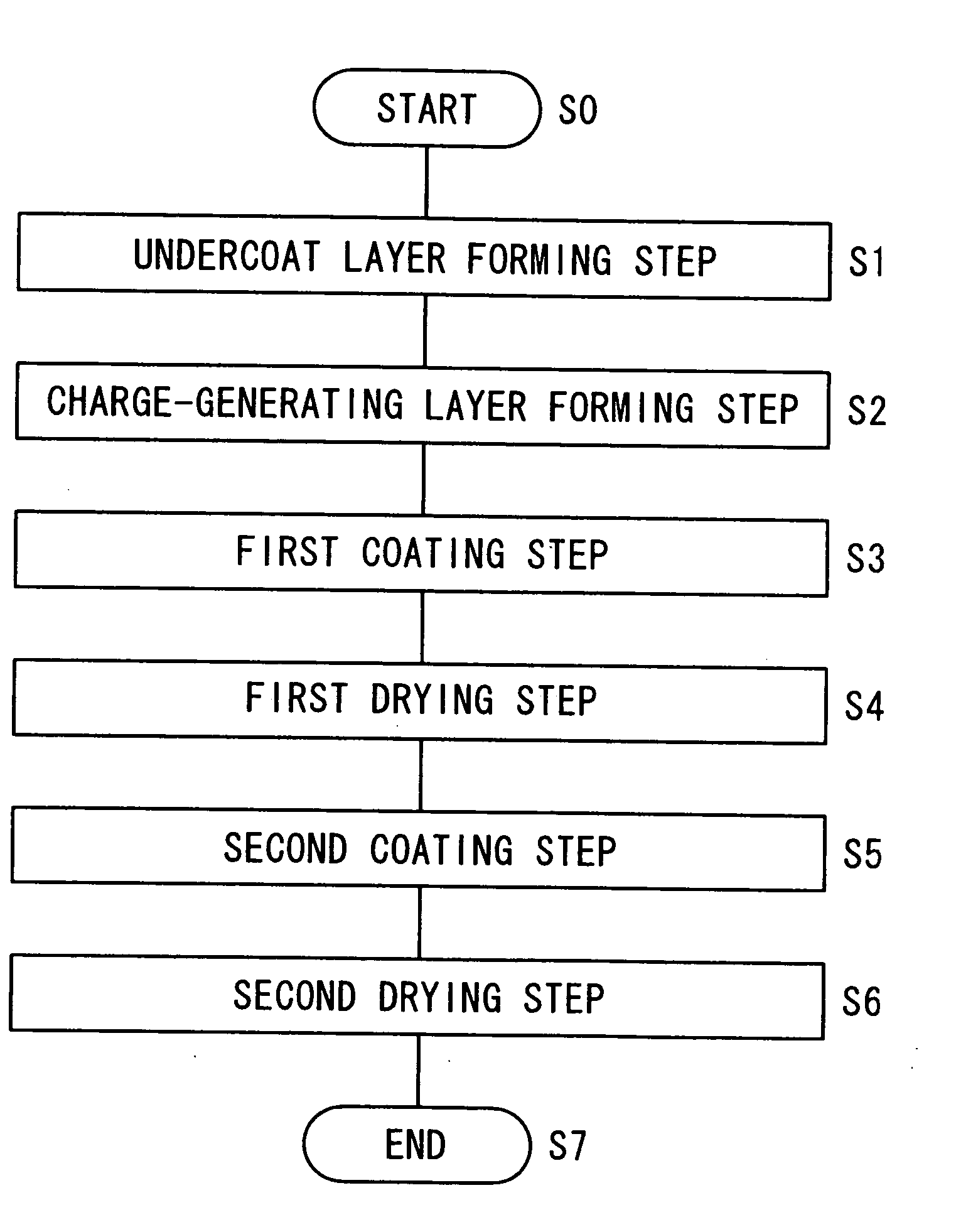
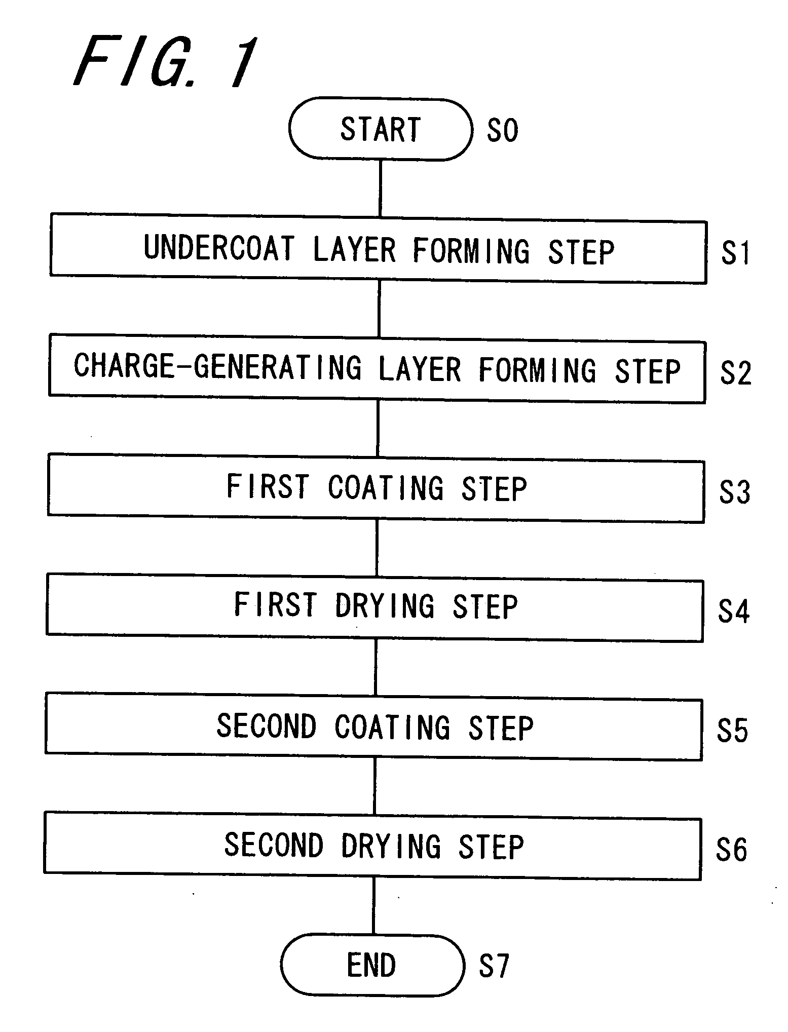
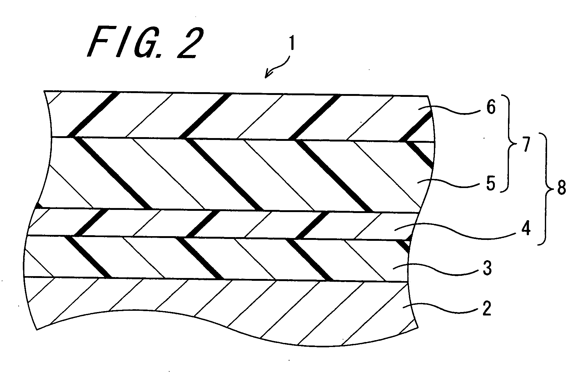
[0203] An undercoat layer forming step, a charge-generating layer forming step, a first coating step, a first drying step, a second coating step and a second drying step were carried out in the manner mentioned below, thereby forming an undercoat layer, a charge-generating layer, a first charge-transporting layer and a second charge-transporting layer, on the outer peripheral surface of a cylindrical conductive substrate of aluminium having an outer diameter of 30 mm and a length in the lengthwise direction of 346 mm to construct a photoreceptor of Example 1.

Undercoat Layer-Forming Step:

[0204] 3 parts by weight of titanium oxide (trade name, TTO-D1 (dendritic rutile type surface-treated with Al2O3 and ZrO2, having a titanium content of 85%), by Ishihara Sangyo), and 3 parts by weight of alcohol-soluble nylon resin (trade name, CM8000, by Toray) were added to a mixed solvent of 60 parts by weight of methanol and 40 parts by weight of 1,3-dioxolan, and dispersed with a paint shaker...

example 2

[0210] A photoreceptor of Example 2 was produced in the same manner as in Example 1, for which, however, the hindered phenol compound of the structural formula (1ac) was used as the sublimable antioxidant.

example 3

[0211] A photoreceptor of Example 3 was produced in the same manner as in Example 1, for which, however, the heating temperature in the first drying step was 135° C.


PUM

PropertyMeasurementUnit
temperatureaaaaaaaaaa
pressureaaaaaaaaaa

Abstract

An method for producing an electrophotographic proreceptor includes a first coating step of applying a coating liquid containing a sublimable antioxidant and a photoconductive substance, onto a conductive substrate to form a first coating film thereon, a first drying step of drying the formed first coating film by heating to form a first photosensitive layer, a second coating step of applying the coating liquid used in the first coating step, onto the first photosensitive layer to form a second coating film, and a second drying step of drying the formed second coating film by heating to form a second photosensitive layer. In the second drying step, the drying condition is made to differ from the drying condition in the first drying step so that a degree of sublimation of the antioxidant in the second drying step is lower than that of sublimation of the antioxidant in the first drying step.

Description

CROSS-REFERENCE TO RELATED APPLICATION [0001] This application claims priority to Japanese Patent Application No. JP 2005-362382, which was filed on Dec. 15, 2005, the contents of which, are incorporated herein by reference, in their entirety. BACKGROUND OF THE INVENTION [0002] 1. Field of the Invention [0003] The present invention relates to a method for producing an electrophotographic photoreceptor, and to an electrophotographic photoreceptor and an image forming apparatus. [0004] 2. Description of the Related Art [0005] An electrophotographic photoreceptor (hereinafter this may be simply referred to as “photoreceptor”) has a constitution of a photoconductive substance-containing photosensitive layer laminated on a conductive substrate. One example of the electrophotographic photoreceptor is an inorganic photoreceptor in which the photosensitive layer comprises an inorganic photoconductive substance such as selenium, zinc oxide or cadmium sulfide as the essential ingredient there...

Claims


Application Information

Patent Timeline
Patent Type & Authority Applications(United States)
IPC IPC(8): G03G5/047
CPCG03G5/047G03G5/0517G03G5/0525Y10S430/103
Inventor KIHARA, AKIKOMATSUO, RIKIYA
Owner SHARP KK
Why Eureka
Try Eureka