Controlled combustion for regenerative reactors

a regenerative reactor and controlled combustion technology, applied in the direction of metal/metal-oxide/metal-hydroxide catalyst, energy input, hydrocarbon by hydrocarbon cracking, etc., can solve the problems of reducing the durability of the reactor system, affecting the efficiency of the reactor, and difficult to fabricate and maintain carefully-dimensioned shapes for use at high temperatures

Active Publication Date: 2007-06-28
EXXON RES & ENG CO
View PDF6 Cites 103 Cited by
  • Summary
  • Abstract
  • Description
  • Claims
  • Application Information

AI Technical Summary

Problems solved by technology

All of these systems suffer disadvantages.
Positioning nozzles, distributors, or burners in the middle of the regenerative flow path of the reactor diminishes the durability of the reactor system.
It is very difficult to fabricate and maintain carefully-dimensioned shapes for use at high temperatures.
If the nozzles or distributor loses its carefully-dimensioned shape, it will no longer produce uniform flame temperatures.
A further disadvantage of using nozzles, d

Method used


Image

  • Controlled combustion for regenerative reactors
  • Controlled combustion for regenerative reactors
  • Controlled combustion for regenerative reactors

Examples


example 1

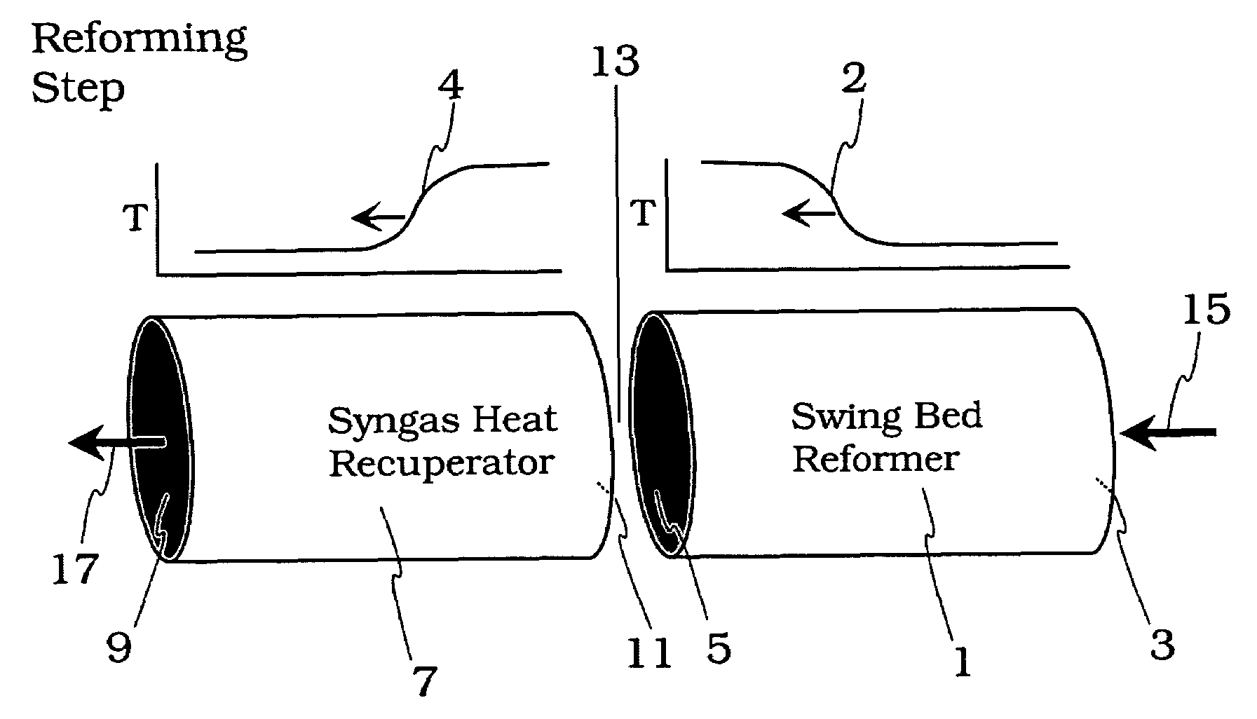
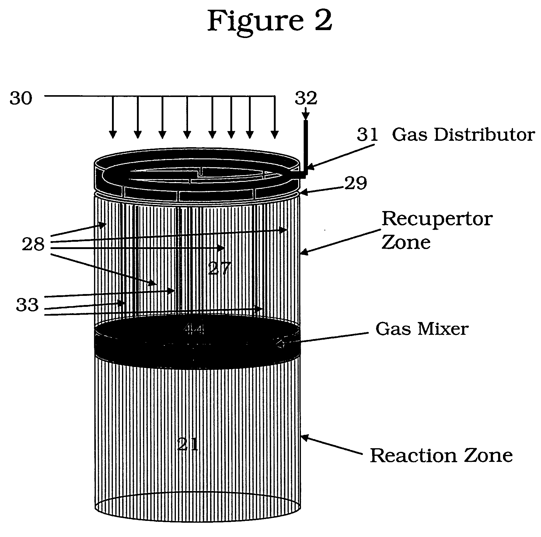
[0050]The following is an example of an asymmetric reverse-flow reactor system used to perform methane steam reforming. The reactor is used in the orientation shown in FIG. 2, with the endothermic reforming step flowing upwards through the reactor (not shown) and exothermic fuel combustion step flowing downwards through the reactor (as illustrated). The diameter of the reactor (inside of insulation) is 2.5 inches. The bed components have diameters of about 2.5 inches to fit within the insulation. The reforming or reaction zone (21) is comprised of a 2.5 inch length of 400 cells / in2 honeycomb that has been wash-coated with reforming catalyst.

[0051]The recuperator zone (27) was constructed of several lengths of uncatalyzed 400 cells / in2 honeycomb located at the inlet end that are stacked for a combined height of 1.19 inches.

[0052]A distributor means (31) illustrated in FIGS. 2 and 3 was located above the recuperator honeycomb. It comprised a 1.8 inch diameter ring of 0.25 inch (OD) st...

example 2

[0059]The controlled combustion reverse flow regenerative reaction may be employed for Regenerative Thermal Oxidation (“RTO”) processes. The RTO processes are conventionally used to combust relatively low levels of contaminants from a larger stream of air. FIG. 5a illustrates the conventional configuration of an RTO reactor, FIG. 5b a RTO reverse flow reactor with controlled combustion.

[0060]Referring to FIG. 5a, the process is generally comprised of two regenerative bodies (501, 502) with a burner (503) in between. Contaminated air (504) is heated in the first regenerative body (501), supplemental heat is provided by the combustion of fuel (505) in burner (503) situated between the two regenerative bodies, and the products are cooled to exit the second regenerative body as clean air (506). Frequent flow reversal, switching to streams (504a &506a), is used to keep the sensible heat (of heating or cooling) moving back and forth between the two bodies (501, 502). All or part of the re...

example 3

Autothermal Reforming (“ATR”)

[0063]The controlled combustion reverse flow regenerative reactor may be employed for Autothermal Reforming (“ATR”). In the RTO application, the amount of oxidant (air) is conventionally many times greater than the amount needed for stoichiometric combustion of the contaminants and the supplemental fuel. Also, the incoming contaminated air is near ambient conditions of pressure and temperature. For ATR, the oxidant is present in sub-stoichiometric amounts, and may be absent of any diluents. The fuel is not a supplementary material, but a feedstock to be reformed. Pressures and feed temperature are typically substantially higher. These differences notwithstanding, the application includes substantially the same components as the RTO application and is illustrated in FIG. 5b. Preferably, the feed stream (504) in largest volume flow rate will be distributed into the majority of regenerative body (501) channels via the entry distribution volume (507). The fe...


PUM

PropertyMeasurementUnit
Temperatureaaaaaaaaaa

Abstract

The overall efficiency of a regenerative bed reverse flow reactor system is increased where the location of the exothermic reaction used for regeneration is suitably controlled. The present invention provides a method and apparatus for controlling the combustion to improve the thermal efficiency of bed regeneration in a cyclic reaction/regeneration processes. The process for thermal regeneration of a regenerative reactor bed entails
    • (a) supplying the first reactant through a first channel means in a first regenerative bed and supplying at least a second reactant through a second channel means in the first regenerative bed,
    • (b) combining said first and second reactants by a gas mixing means situated at an exit of the first regenerative bed and reacting the combined gas to produce a heated reaction product,
    • (c) passing the heated reaction product through a second regenerative bed thereby transferring heat from the reaction product to the second regenerative bed.

Description

FIELD OF THE INVENTION[0001]The present invention relates broadly to regenerative reactors. More particularly the invention relates to an improved process and apparatus for controlling combustion for thermal regeneration of reverse flow regenerative reactors in a unique and thermally efficient way.BACKGROUND OF THE INVENTION[0002]Regenerative reactors are conventionally used to execute cyclic, high temperature chemistry. Typically, regenerative reactor cycles are either symmetric (same chemistry or reaction in both directions) or asymmetric (chemistry or reaction changes with step in cycle). Symmetric cycles are typically used for relatively mild exothermic chemistry, examples being regenerative thermal oxidation (“RTO”) and autothermal reforming (“ATR”). Asymmetric cycles are typically used to execute endothermic chemistry, and the desired endothermic chemistry is paired with a different chemistry that is exothermic (typically combustion) to provide heat of reaction for the endothe...

Claims


Application Information

Patent Timeline
IPC IPC(8): C10G47/00C10G9/36C07C5/00C07C1/00C07C4/02
CPCB01F3/02B01F5/0603B01F2215/0431B01J4/002B01J8/02B01J8/0278B01J8/04B01J8/0438B01J8/0442B01J8/0492B01J8/0496B01J19/2485B01J19/26B01J2208/00132B01J2208/00309B01J2208/00504B01J2208/0053B01J2208/00831B01J2208/0084B01J2208/00849B01J2219/0004B01J2219/00081B01J2219/00117B01J2219/00157B01J2219/00159B01J2219/182B01J2219/1943C01B3/46C01B2203/0233C01B2203/0238C01B2203/0244C01B2203/0261C01B2203/0277C01B2203/0811C01B2203/0844C01B2203/1235C01B2203/1241C01B2203/142C07C5/327C08G18/10C08G18/4825C08G18/73C08G18/792C08G2101/005C07C11/24C08G18/3203C08G18/48Y10S585/943C07C2/78Y02P20/129C08G2110/005B01F23/10B01F25/421
Inventor HERSHKOWITZ, FRANKFREDERICK, JEFFREY W.
Owner EXXON RES & ENG CO
Why Eureka
Try Eureka