Motor system, control method thereof, and compressor using the same

a control method and motor technology, applied in the direction of dynamo-electric converter control, dynamo-electric gear control, dynamo-electric brake control, etc., can solve the problems of poor noise characteristic of vector control system, limited range of maximum driving for the same load torque, and less accurate than, etc., to achieve low cost, simple circuit, and high performance

Inactive Publication Date: 2007-07-05
SAMSUNG ELECTRONICS CO LTD
View PDF4 Cites 63 Cited by
  • Summary
  • Abstract
  • Description
  • Claims
  • Application Information

AI Technical Summary

Benefits of technology

[0014]Accordingly, it is an aspect of the present invention to provide a motor system with a simp...

Problems solved by technology

However, this type of a 120-degree driving system has disadvantages, such as, for example, a poor noise characteristic over a vector control system and a limited range of maximum driving for the same load torque due to a small conduction angle.
However, since such a position estimation algorithm has relatively many errors and requires the positional information for the d-q axis conversion, it is less accurate than when a position sensor such as a rotary encoder is used.
However, the vector control method employing the position estimation algorithm has a structure simpler than a structure including the position sensor, which is relatively expensive and has to be attached to a mechanical unit of the motor.
However, the above-menti...

Method used


Image

  • Motor system, control method thereof, and compressor using the same
  • Motor system, control method thereof, and compressor using the same
  • Motor system, control method thereof, and compressor using the same

Examples


first embodiment

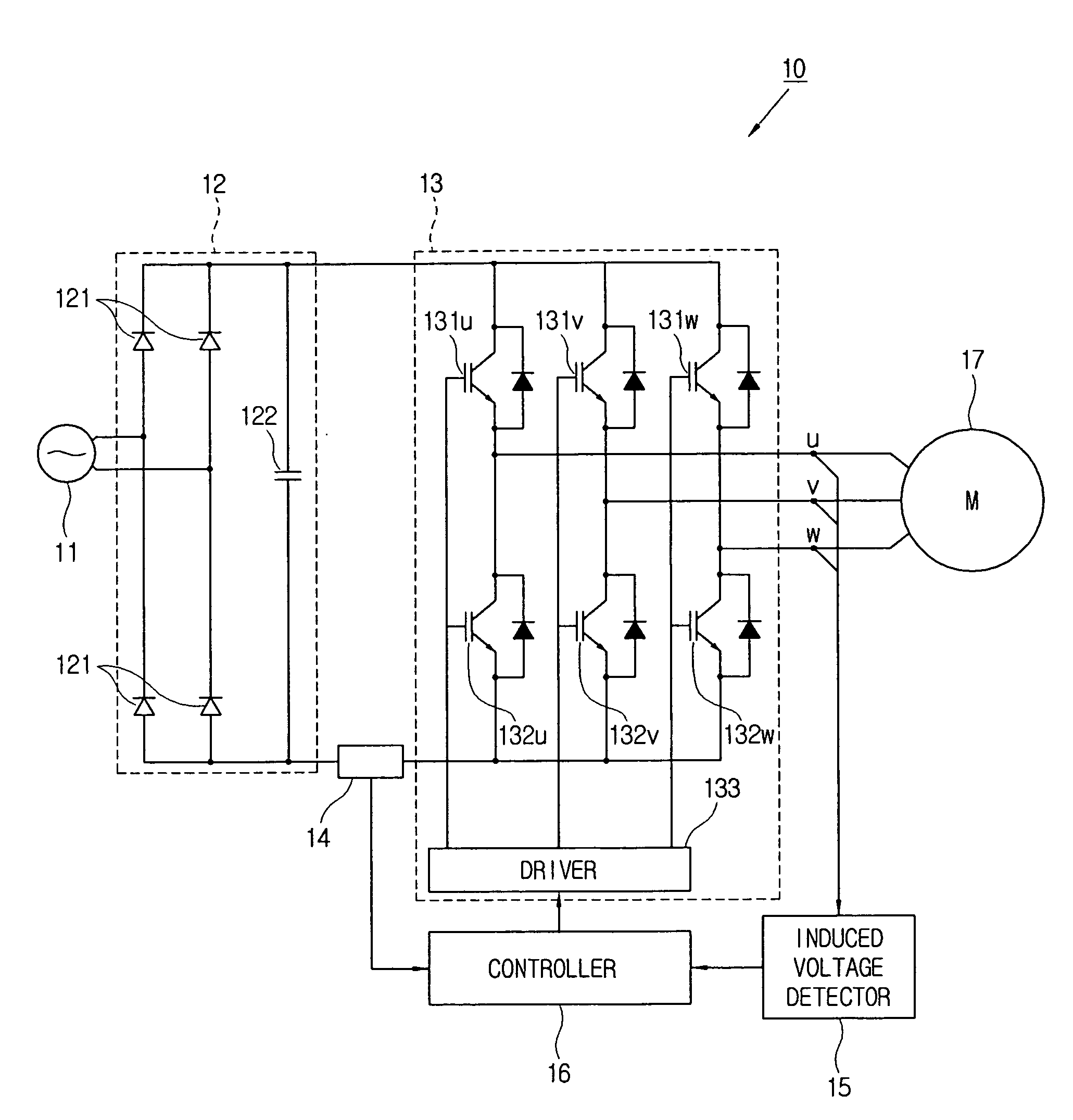
[0047]FIG. 3 is a block diagram illustrating a configuration of a motor system 10 according to the present invention. The motor system 10 includes a BLDC motor 17, an inverter 13 driving the BLDC motor 17, a current detector 14 detecting a direct current of the inverter 13, an induced voltage detector 15 detecting an induced voltage of the BLDC motor 17 and a controller 16 controlling at least one of an output voltage and an output frequency of the inverter 13 based on the detected direct current and the detected induced voltage.

[0048]The BLDC motor 17 includes a stator having three coils arranged in three phases and a rotator (i.e., a rotor) arranged rotably with respect to the stator.

[0049]The motor system 10 may further include a converter 12 receiving an alternating current from a commercial power source 11 and converting the received alternating current into a direct current. The converter 12 includes four diodes 121 configured in the form of a two-phase bridge and a smoothing ...

second embodiment

[0066]Next, the estimation of the motor current in the motor system 10 according to this second embodiment will be described. As shown in FIG. 6, the controller 16 controls the driver 133 to perform the PWM operation for only one of two or three switching elements 131u-w and 132u-w, which are switched on. This is called “single-phase ARM modulation”. On the other hand, the PWM operation for two of a plurality of switching elements is called “two-phase ARM modulation”.

[0067]For typical sinusoidal PWM, three-phase ARM modulation is used and PWM duty cycles are varied depending on the phase are output to the U, V and W phases. Accordingly, for the sinusoidal PWM, since a current is complicatedly varied in one period of the carrier frequency and there is a need of a high-speed A / D conversion and a complex timing generation technique in order to detect the motor current from a direct current through an A / D conversion, an expensive high-speed CPU is required.

[0068]However, as in the motor...


PUM


Abstract

A motor system includes a BLDC (brushless direct current) motor; an inverter driving the BLDC motor; a current detector detecting a direct current of the inverter; an induced voltage detector detecting an induced voltage of the BLDC motor; and a controller controlling at least one of an output voltage and an output frequency of the inverter based on the direct current detected by the current detector and the induced voltage detected by the induced voltage detector.

Description

CROSS-REFERENCE TO RELATED APPLICATIONS[0001]This application claims the benefit of Korean Patent Application No. 2005-0133857, filed on Dec. 29, 2005, in the Korean Intellectual Property Office, the disclosure of which is incorporated herein by reference.BACKGROUND OF THE INVENTION[0002]1. Field of the Invention[0003]The present invention relates to a motor system, a control method thereof, and a compressor using the same, and more particularly, to a motor system with a simple circuit, low cost, and high performance, a control method thereof, and a compressor using the same.[0004]2. Description of the Related Art[0005]A typical motor system including a motor such as a BLDC (brushless direct current) generally includes a converter to convert an alternating power source into a direct power source, an inverter to invert the direct power source to an alternating power source to be provided to the BLDC motor, an induced voltage detector to detect a position of a motor rotator and a cont...

Claims


Application Information

Patent Timeline
IPC IPC(8): H02P21/00
CPCH02P6/182H02P29/0088H02P2209/07H02P29/68H02P27/08H02P2209/09Y10S388/9281Y10S388/912
Inventor HAMAOKA, KOJIYOO, HAN-JOOPARK, PYEONG-KISEO, JEONG-HOOH, KWANG-KYOBAE, HUN-YUBKIM, YUN-JEONG
Owner SAMSUNG ELECTRONICS CO LTD
Why Eureka
Try Eureka