Controller of electric vehicle

a technology of electric vehicles and controllers, applied in the direction of battery/fuel cell control arrangements, electric devices, electrochemical generators, etc., can solve the problem of inability to prevent battery performance degradation, and achieve the effect of preventing battery performance degradation

Inactive Publication Date: 2007-07-05
HONDA MOTOR CO LTD
View PDF4 Cites 40 Cited by
  • Summary
  • Abstract
  • Description
  • Claims
  • Application Information

AI Technical Summary

Benefits of technology

[0008]However, in both technologies described in JP H05-262144A and JP 2001-130268, a battery is controlled while a vehicle is running or while the vehicle is stopping and the battery is being charged from an external charger. Therefore, it is impossible to prevent battery performance degradation in a state (referred to as a soak state, hereafter) where the electric vehicle is stopping and a high-voltage secondary cell (storage battery) is not being charged or discharged.
[0009]It is an object of the present invention to provide a controller of an electric vehicle which can prevent performance degradation of a storage battery.
[0011]The controller with such a structure selectively or simultaneously drives at least one of the fan and the air conditioner depending on the temperature detected by the temperature sensor and the state of charge value detected by the state of charge value sensor after detecting the stop request of the electric vehicle. Accordingly, the temperature and the state of charge value of the storage battery decrease. As a result, it is possible to prevent performance degradation of the storage battery.
[0013]In the controller installed in the electric vehicle according to the present invention, if the temperature detected by the temperature sensor exceeds a predetermined temperature and the state of charge value detected by the state of charge value sensor exceeds a predetermined state of charge value, the cooling control means may selectively or simultaneously drive at least one of the fan and the air conditioner. The controller with such a structure can reduce volume of data since the predetermined temperature and the predetermined state of charge value are used instead of the state of charge value set corresponding to the temperature detected by the temperature sensor.
[0014]In the controller installed in the electric vehicle according to the present invention, if the state of charge value detected by the state of charge value sensor exceeds a predetermined state of charge value set corresponding to the temperature detected by the temperature sensor, the cooling control means may drive the fan. In addition, if the state of charge value detected by the state of charge value sensor exceeds the predetermined state of charge value set corresponding to the temperature detected by the temperature sensor and at least one of the temperature detected by the temperature sensor and the state of charge value detected by the state of charge value sensor exceeds a respective predetermined value, the cooling control means may drive the fan and the air conditioner together. When the temperature is not so high and only a little decrease of the state of charge value is required, the controller with such a structure can prevent the state of charge value from decreasing more than necessary.

Problems solved by technology

Therefore, it is impossible to prevent battery performance degradation in a state (referred to as a soak state, hereafter) where the electric vehicle is stopping and a high-voltage secondary cell (storage battery) is not being charged or discharged.

Method used


Image

  • Controller of electric vehicle
  • Controller of electric vehicle
  • Controller of electric vehicle

Examples


first embodiment

[0041]Next, here will be described a controller (control unit) in an electric vehicle according to an embodiment of the present invention in detail, referring to the accompanying drawings. The same elements or parts are designated with the same references throughout the drawings.

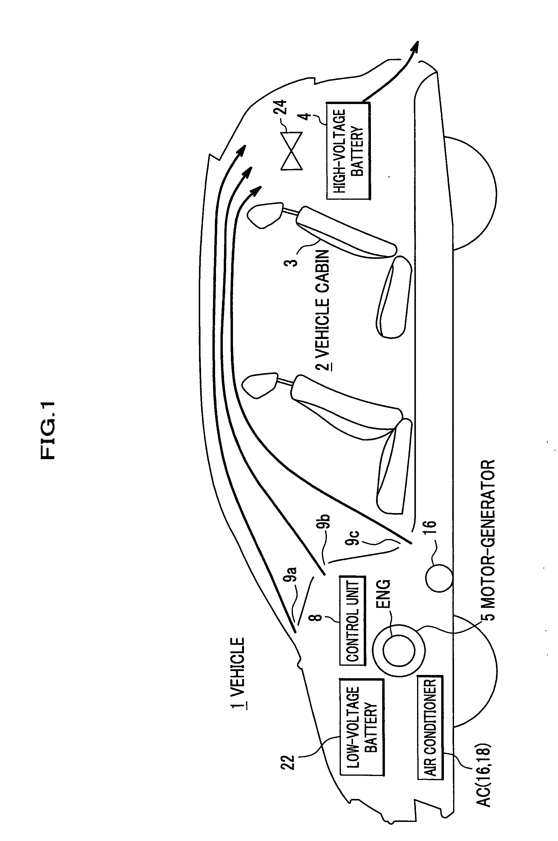
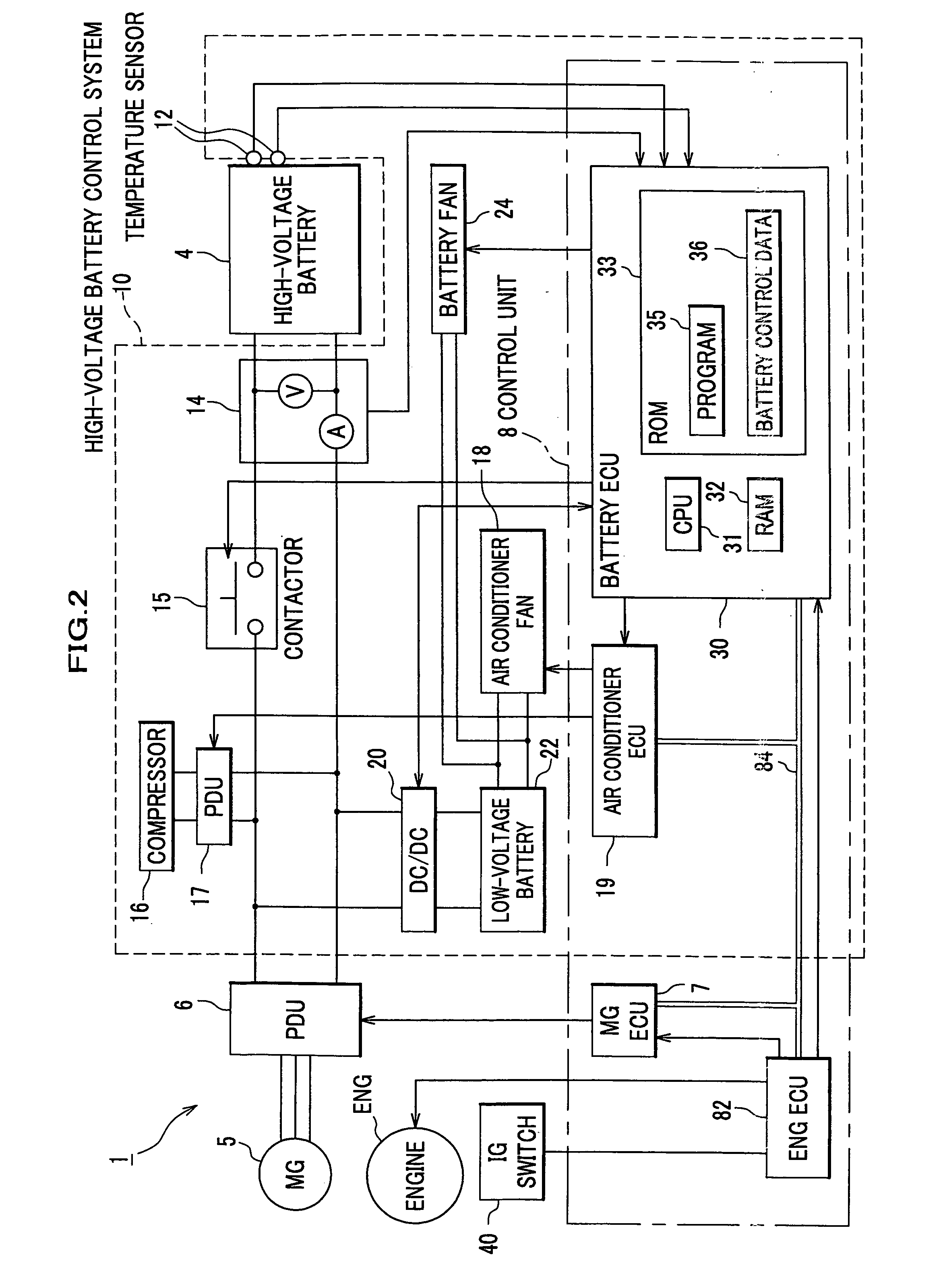
[0042]First of all, referring to FIGS. 1 and 2, here will be described a structure of an electric vehicle (referred to as “a vehicle”, hereafter) including a high-voltage battery control system and a battery ECU (Electrical Control Unit).

[0043]FIG. 1 is a schematic sectional view of a vehicle which uses a high-voltage battery (storage battery) including a lithium-ion battery and can prevent performance degradation of the storage battery during a soak (in a soak state where the vehicle is stopping and the storage battery is not being charged or discharged) according to the embodiment. FIG. 2 is a schematic principal block diagram conceptually showing a structure of the vehicle 1 focusing on a high-voltage bat...

second embodiment

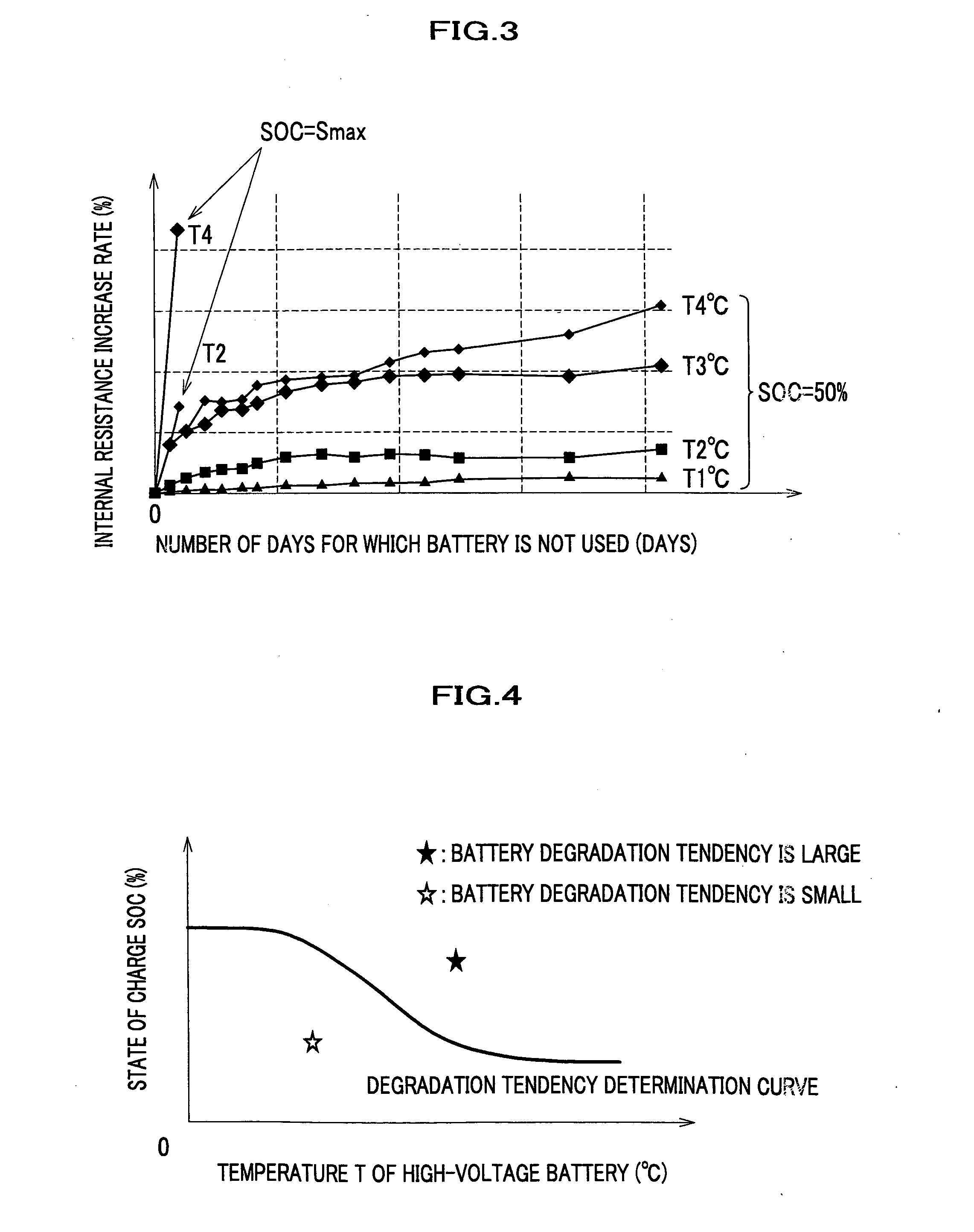
[0076]FIG. 8 is a diagram illustrating battery control data 36 used in the second embodiment. FIG. 9 is a flowchart showing a process flow of Step S58a for preventing degradation performed in the second embodiment instead of Step S58 for preventing the degradation in FIG. 6. In the embodiment, as shown in FIG. 8, besides the degradation tendency determination curve data, a predetermined temperature Ttha is used.

[0077]In Step S56 in FIG. 6, when it is determined that the degradation tendency is large (“Yes”), the process proceeds to Step S58a. As shown in FIG. 9, in Step S70 in Step S58a, the contactor 15 is turned on so that the battery fan 24 is driven. Then, the process proceeds to Step S72. After that, the battery ECU 30 determines whether the battery temperature T exceeds the predetermined temperature Ttha. When the battery temperature T dose not exceed the predetermined temperature Ttha (“No”), the process of Step S58a ends (, that is, only the battery fan 24 is driven). Then, ...

third embodiment

[0080]FIG. 10 is a diagram illustrating a degradation tendency determination curve used in the third embodiment. FIG. 11 is a flowchart showing a process flow of Step S58b for preventing degradation performed in the third embodiment instead of Step S58 for preventing degradation in FIG. 6. As shown in FIG. 10, in the third embodiment, besides the degradation tendency determination curve data, a predetermined temperature Ttha and a predetermined SOC value SOCtha are used.

[0081]Except that Step S72 shown in FIG. 9 is replaced with Step S72a, Step S58b is same with Step S58a. To describe the difference, in Step S72a, it is determined whether the battery temperature T exceeds the predetermined temperature Ttha and the SOC value SOC exceeds the predetermined SOC value SOCtha.

[0082]Therefore, according to the embodiment, in a case where the SOC value SOC is higher than the SOC threshold SOCth, both of the battery fan 24 and the air conditioner AC are driven when the battery temperature T ...


PUM

PropertyMeasurementUnit
voltageaaaaaaaaaa
stores poweraaaaaaaaaa
temperatureaaaaaaaaaa

Abstract

A controller in the electric vehicle is provided in which data which are criteria to determine a magnitude of degradation tendency of a high-voltage secondary cell are stored in a ROM in a high-voltage battery electrical controller. When it is detected that an ignition switch is turned off, the magnitude of the degradation tendency is determined depending on a temperature of the high-voltage secondary cell and a state of charge value based on the data. When it is determined that the degradation tendency is large, the battery fan and the air conditioner are operated so that the state of charge value and the temperature decrease. Next, while repeating determination of the magnitude of the degradation tendency, when it is determined that the degradation tendency is small, the operation of the battery fan and the air conditioner is stopped. Therefore, the state of charge value is prevented from decreasing more than necessary.

Description

CROSS REFERENCE TO RELATED APPLICATIONS[0001]This application claims the foreign priority benefit under Title 35, United States Code, §119(a)-(d) of Japanese Patent Application No. 2006-000065, filed on Jan. 4, 2006 in the Japan Patent Office, the disclosure of which is herein incorporated by reference in its entirety.BACKGROUND OF THE INVENTION[0002]1. Field of the Invention[0003]The present invention relates to a controller installed in an electric vehicle including a storage battery in which the higher values of temperature and state of charge are, the larger performance degradation tendency is.[0004]2. Description of the Related Art[0005]A lithium-ion battery is used in an electric vehicle such as an electric car, a fuel cell car, and a hybrid car to supply power to a drive motor and to store power regenerated by the drive motor and power generated by a fuel cell. The lithium-ion battery with a higher temperature and SOC (State Of Charge) value can be more easily degraded. As fo...

Claims


Application Information

Patent Timeline
Patent Type & Authority Applications(United States)
IPC IPC(8): H02J7/04B60L3/00B60L11/18B60R16/04H01M10/48H01M10/60H01M10/613H01M10/625H01M10/633H01M10/6556H01M10/6563
CPCB60H1/00278Y02T10/705B60H2001/003B60K1/04B60K2001/005B60L11/1861B60L11/187B60L11/1872B60L11/1874B60L2260/56B60W2510/244B60W2510/246Y02T10/7005Y02T10/7011Y02T10/7044B60H1/00392B60L2240/545B60L58/16B60L58/25B60L58/26B60L58/15Y02T10/70
Inventor SASAKI, TAKAHIROWAKASHIRO, TERUO
Owner HONDA MOTOR CO LTD
Why Eureka
Try Eureka