Multi-stage refrigerant turbine

a multi-stage refrigerant turbine and turbine technology, which is applied in the direction of machines/engines, mechanical equipment, light and heating apparatus, etc., can solve the problems of limiting the use and reliability of solar power panels, requiring fuels that are not readily renewable or non-renewable, and reducing operating and maintenance expenses. , the effect of increasing the operating li

Inactive Publication Date: 2007-07-12
MCPHAIL RICHARD JR
View PDF16 Cites 9 Cited by
  • Summary
  • Abstract
  • Description
  • Claims
  • Application Information

AI Technical Summary

Benefits of technology

[0014] It is a still further object of the present invention to provide an apparatus and method of the above type that provides a safe, efficient closed loop system for generating electricity.
[0015] It is a still further object of the present invention to provide an apparatus and method of the above type that may be constructed using less costly materials of construction because of the more moderate operating conditions.
[0016] It is a still further object of the present invention to provide an apparatus and method of the above type that provides for reduced operating and maintenance expenses and for increased operating life.
[0017] It is a still further object of the present invention to provide an apparatus and method of the above type that makes efficient use of waste heat from other processes.
[0018] It is a still further object of the present invention to provide an apparatus and method of the above type that allows waste heat from a wide variety of sources to be used to provide a reliable source of A / C power.
[0019] Toward the fulfillment of these and other objects and advantages, the present invention comprises a multi-stage, refrigerant driven turbine, a closed loop system into which it is incorporated, and a method of operating the system. A multi-stage refrigerant driven turbine is incorporated into a closed loop system to generate electricity. Heat transfer conduits and optional flow diverting members are disposed between the rotor blades of each stage of the turbine. The closed loop system also includes a condenser, pump, refrigerant storage container, refrigerant, and expansion valve. A heat source and heat sink are also provided. The expansion valve introduces a saturated refrigerant mist into the turbine, and the refrigerant expands as it flashes to a gas, thereby rotating the rotor blades and turbine shaft. Heat from the heat source is added between stages to increase the portion of refrigerant converted to gas. The gas is passed from the turbine, condensed, and passed as a liquid to storage or to repeat the cycle. The blending of refrigeration cycle and turbine technologies allows electricity to be generated in a closed loop system under moderate conditions.

Problems solved by technology

Solar power panels are known in the art but are limited in their use, because they generate DC power only.
Still, difficulties in finding appropriate locations for windmills, and fluctuations in wind force and direction limit their use and reliability.
For example, these turbines require fuels that are non-renewable or that are not readily renewable.
The extreme conditions typically encountered in these turbines also adds to the cost and complexity of the equipment and materials of construction that must be used.
These extreme conditions also lead to high maintenance cost, increased wear and tear, and short equipment life.
The high energy input needed to maintain the extreme conditions also leads to high cost for power generation.
Still, the use of a compressor in a refrigeration cycle increases the cost and complexity of the system and also increases the energy consumption and therefore operation cost of the system.
Using a compressor can also add to the cost and complexity of maintaining a refrigeration cycle.

Method used


Image

  • Multi-stage refrigerant turbine
  • Multi-stage refrigerant turbine

Examples


Embodiment Construction

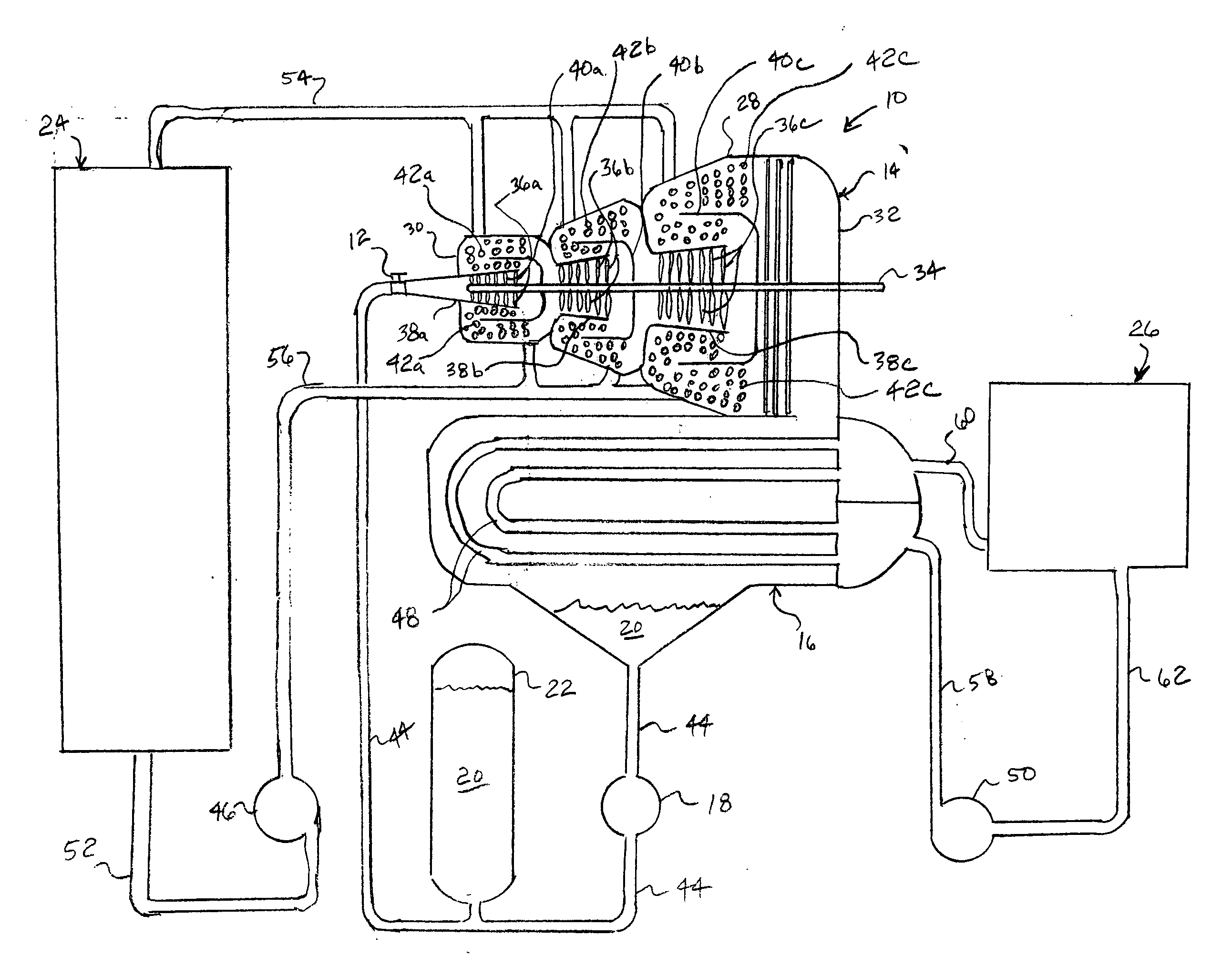
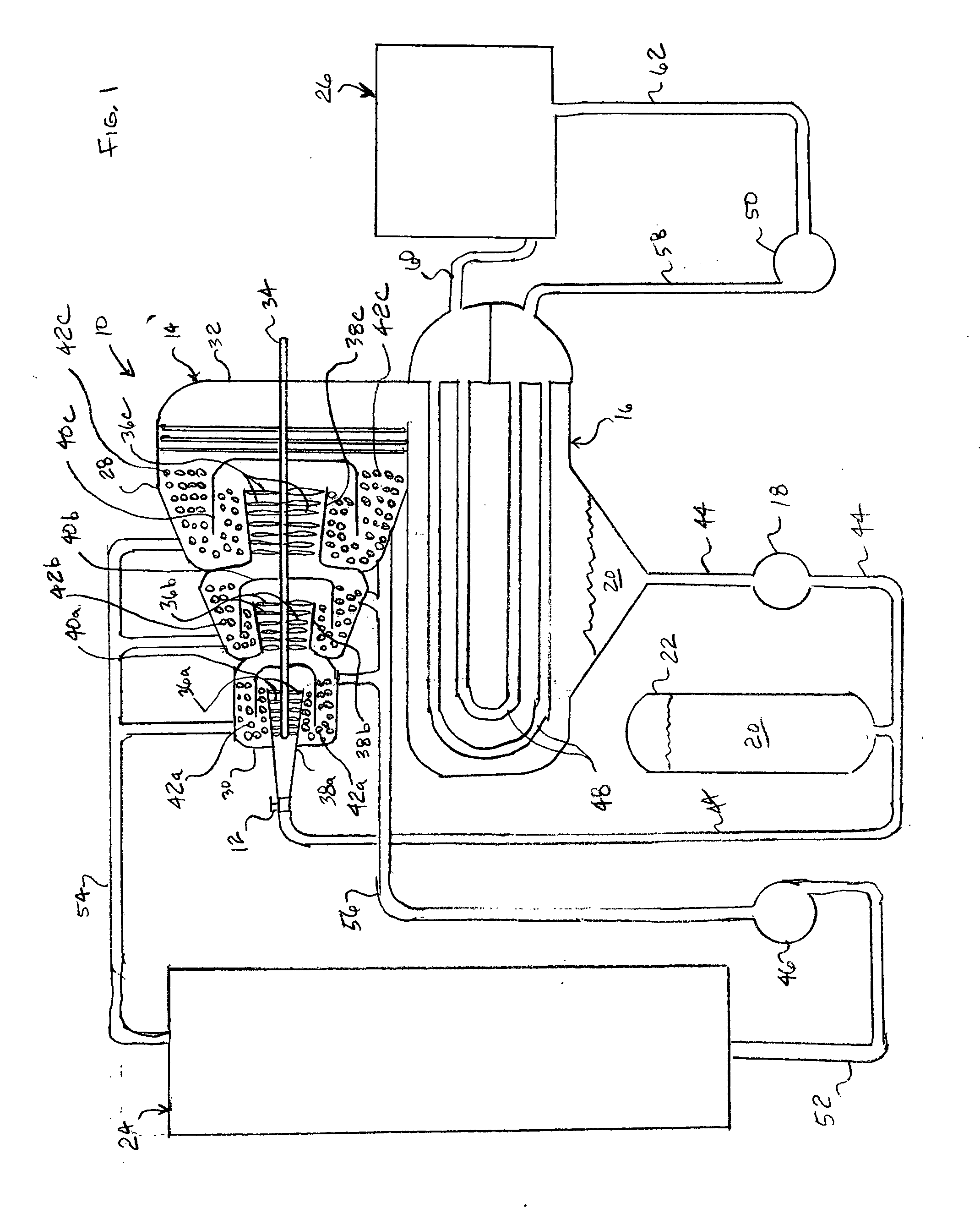
[0022] Referring to FIG. 1, reference numeral 10 refers in general to a refrigerant system of the present invention. The system includes an expansion valve 12, a turbine 14, a condenser 16, a pump 18, and refrigerant 20 and may include a refrigerant storage reservoir or container 22. A heat source 24 and heat sink 26 are also provided.

[0023] The expansion or throttling valve 12 of the refrigerant system 10 may take the form of any number of different commercially available throttle valves or spray nozzles. The valve 12 has speed or load governing controls, and the size and capacity of the valve depend upon a variety of system parameters, such as size and operating conditions. Multiple valves 12 may be used and may be positioned at different locations to help control load. The valve 12 may also admit refrigerant 20 directly to the turbine 14, or may admit the refrigerant to an evaporator or heat exchanger before the refrigerant 20 is passed to the turbine 14.

[0024] In a preferred e...


PUM


Abstract

A multi-stage refrigerant driven turbine is incorporated into a closed loop system to generate electricity. Heat transfer conduits and optional flow diverting members are disposed between the rotor blades of each stage of the turbine. The closed loop system also includes a condenser, pump, refrigerant storage container, refrigerant, and expansion valve. A heat source and heat sink are also provided. The expansion valve introduces a saturated refrigerant mist into the turbine, and the refrigerant expands as it flashes to a gas, thereby rotating the rotor blades and turbine shaft. Heat from the heat source is added between stages to increase the portion of refrigerant converted to gas. The gas is passed from the turbine, condensed, and passed as a liquid to storage or to repeat the cycle. The blending of refrigeration cycle and turbine technologies allows electricity to be generated in a closed loop system under moderate conditions.

Description

BACKGROUND OF THE INVENTION [0001] The present invention relates to electricity generation using a turbine and, more particularly, to electricity generation using a multi-stage turbine. [0002] There has long been a desire to find alternative sources for generating electricity. Solar power panels are known in the art but are limited in their use, because they generate DC power only. Windmills are also well known in the art and have been used for generating AC power. Still, difficulties in finding appropriate locations for windmills, and fluctuations in wind force and direction limit their use and reliability. [0003] Turbines and multi-stage turbines are known in the art. In gas turbines, compressed air is forced into an ignition chamber and combined with fuel, and the fuel is ignited. The expanding, ignited gases travel along the axis of the turbine shaft, imparting motion to rotor blades affixed to the turbine shaft, thereby rotating the shaft. Additional fuel, or after burner fuel,...

Claims


Application Information

Patent Timeline
Patent Type & Authority Applications(United States)
IPC IPC(8): F25B1/00
CPCF01K7/22F22B37/04F01K25/10
Inventor MCPHAIL, RICHARD JR.
Owner MCPHAIL RICHARD JR
Why Eureka
Try Eureka