Over-current protector

Inactive Publication Date: 2007-07-12
INPAQ TECH
View PDF15 Cites 15 Cited by
  • Summary
  • Abstract
  • Description
  • Claims
  • Application Information

AI Technical Summary

Benefits of technology

[0017] The device of the present invention may be manufactured by traditional tools such as a punching machine, soldering machine, mold, and coat

Problems solved by technology

When the fuse is being melted due to the heat, surrounding media will expand rapidly so that the tube will explode.
The arc will

Method used


Image

  • Over-current protector
  • Over-current protector
  • Over-current protector

Examples


embodiment 1

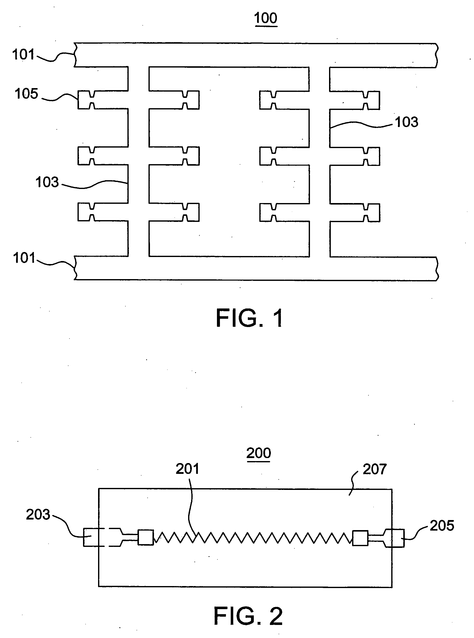
[0025] As shown in FIG. 1, a thin plate is punched to form a frame 100. The frame 100 is formed with bases 101. Plural supporting plates 103 are connected between the bases 101. Plural fusible units 105 are extended from the supporting plates 103. The thin plate is formed by using the following conditions: [0026] 40 wt % PBT (Polybuty Terephthlate), MI=10 g / 10 min, Al(OH)3 of average diameter of 1 μm, short 20 wt % fiber glass of ⅙ inch long, 0.2 wt % anti-oxidant

[0027] The thin plate is formed by a co-rotation bi-helical injection machine (φ=50 mm), wherein the blending temperature is 260-300° C., and the rotation speed of the driving screw is 200 rpm. The length of the fusible unit 105 is 10 mm. The diameter of the fusible unit 105 is 0.13 mm. The fusible unit 105 is coated with a silver layer of 12 μm and a tin layer of 7 μm. The fusible unit is then wound onto a ceramic fiber to form an elongated structure. The frame 100 with the fusible units 105 is put into a mold. Plastic po...

embodiment 2

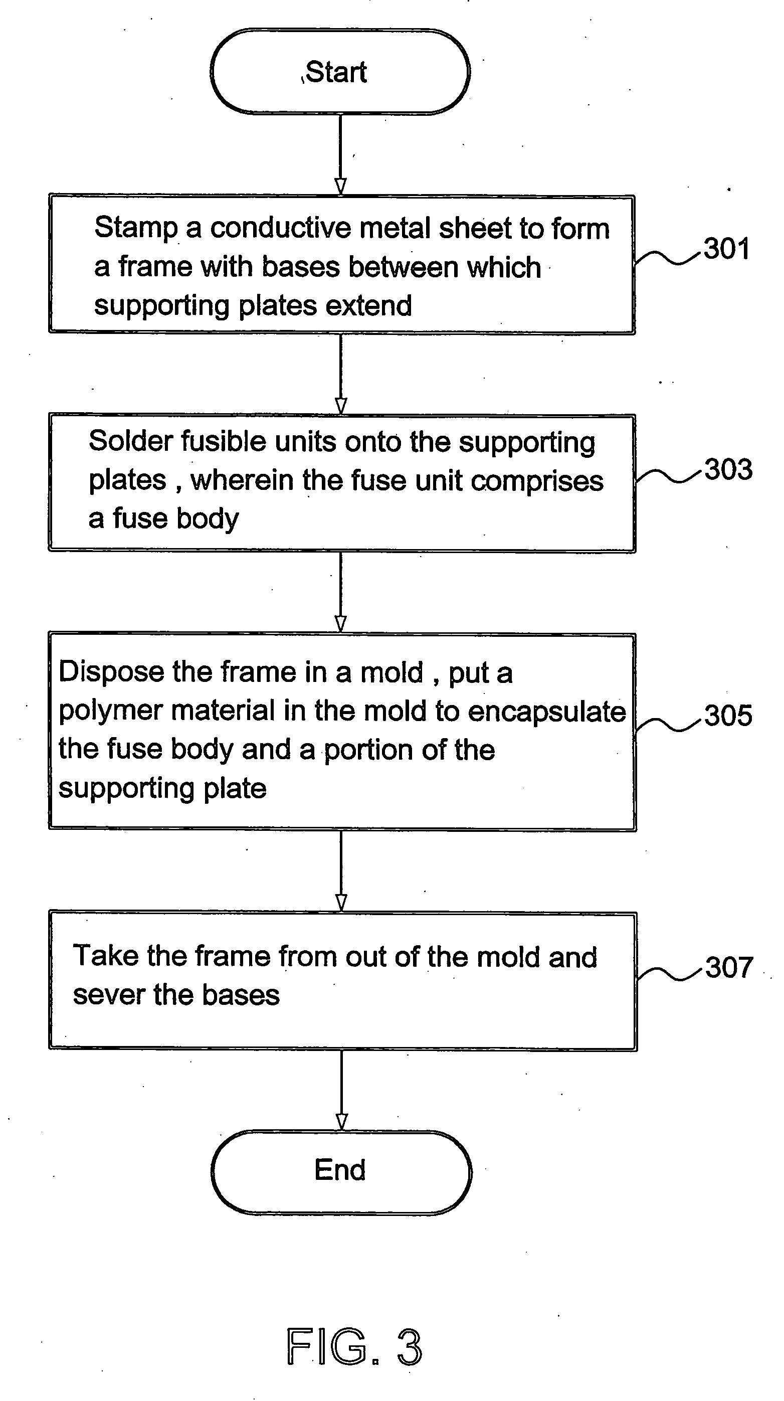
[0033] With reference to FIG. 1 again, an encapsulant material for the fusible unit 105 is the same as that of embodiment 1. A thin plate is punched to form a frame 100. The frame 100 is formed with bases 101. Plural supporting plates 103 are connected between the bases 101. Plural fusible units 105 are extended from the supporting plates 103. The fusible unit 105 is coated by a thermally insulating layer of Teflon of a thickness of 0.1-0.5 mm. The frame 100 with the fusible units 105 is put into a mold. Plastic powder in conjunction with AlOH and glass fiber is injected into the mold to encapsulate the fusible units 105 and a part of the supporting plates 103. The encapsulated fusible unit is then taken from the mold. The bases 101 are cut off, so that a fusible device is provided with two electrode plates at two ends of the fusible device. The method of manufacturing the fusible device comprises steps 301-307 shown in FIG. 3.

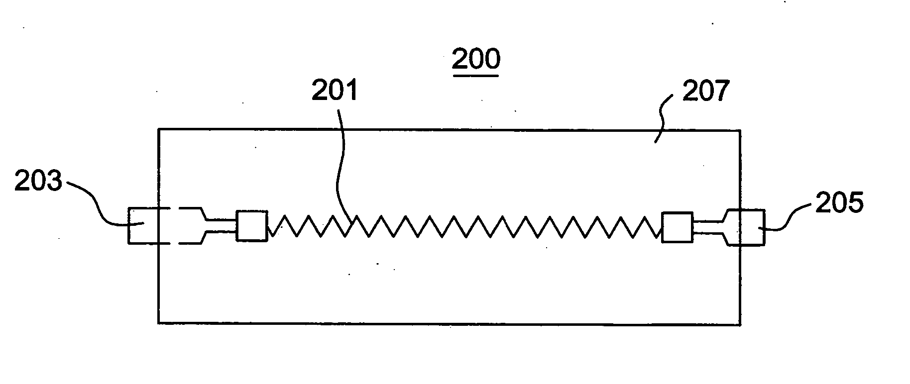
[0034]FIG. 2 shows a fusible device 200 manufactured by...


PUM


Abstract

An over-current protective device is characterized by comprising: a fuse cover, a fusible body disposed therein, and a first electrode and a second electrode respectively extending from the two ends of the fusible body. A method for fabricating the over-current protective device comprises the following steps: stamping a conductive metal sheet to form a frame with a base having two ends respectively extending as a supporting plate, and soldering a fusible unit containing the fusible body between the supporting plates; disposing the frame having the soldered fusible unit into a mold, putting a polymeric material into the mold for covering the fusible body and the supporting plates, and molding the fusible body into a required shape; taking out the frame covered by the polymeric material and cutting the base off so as to obtain an over-current protective device having two electrode plates extending from two ends thereof.

Description

FIELD OF THE INVENTION [0001] The present invention relates to an over-current protector and a method of manufacturing the same, particularly to an over-current protector and a method of manufacturing the same which are used indelicate electronic equipment to protect the equipment. DESCRIPTION OF THE PRIOR ART [0002] A fuse is used to protect an electronic or electrical device in an electric circuit from transient over current or voltage. Therefore, the fuse is an indispensable electronic device. A conventional fuse has a coil or fuse material. The fuse material is sealed in a tube that is made of a glass material, ceramic or other insulating materials. The tube is filled with an insert gas or a filler that may withstand an electric arc. The tube has two conductors at two ends of the tube. The two conductors are connected to a printed circuit board through a soldering contact so that the current may pass the fuse. When the transient current exceeds a predetermined level, the fuse wi...

Claims


Application Information

Patent Timeline
IPC IPC(8): H01H85/38H01H85/18
CPCH01H69/02H01H85/38H01H85/17
Inventor CHANG, KUN-HUANGLIU, WEN-LUNG
Owner INPAQ TECH
Why Eureka
Try Eureka