Fuel cell system

a fuel cell and system technology, applied in the field of fuel cell systems, can solve the problems of degrading the performance of the fuel cell system, the inability of the hydrogen supply means to generate power in the fuel cell to be equipped as infrastructure, and the degradation of the purification ability of the ion exchange resin or the like with time, so as to reduce the water level, suppress the thermal degradation of the ion exchange resin or the like of the water purifier, and increase the temperature

Inactive Publication Date: 2007-07-12
PANASONIC CORP
View PDF2 Cites 19 Cited by
  • Summary
  • Abstract
  • Description
  • Claims
  • Application Information

AI Technical Summary

Benefits of technology

[0051] In accordance with the fuel cell system of the present invention, water that is more likely to decay is discarded from the water storage portion on a regular basis in such a manner that at least a part of water condensed in an interior of the fuel cell system and stored in the water storage portion is discarded at a time in a stop state of the power generation operation, or at least a part of water stored in the water storage portion is discarded at a time in the power generation operation, and at least a part of the water in the water storage portion is replaced by water that is less likely to decay by replenishing cooling water of the fuel cell that has been sterilized by utilizing a heat energy generated in the power generation operation of the fuel cell and is supplied by the water replenishment means from the cooling water circulation portion. Thereby, decay of circulated water is inhibited in the stop state of the power generation operation, and water that is less likely to decay is able to be circulated in the interior of the, fuel cell system during the power generation operation.
[0052] Since the cooler is disposed in the water replenishment passage through which a part of the cooling water is supplied from the cooling water circulation portion to the water storage portion, the cooling water that has cooled the fuel cell and has thereby increased in temperature during the power generation operation can be cooled before being supplied to the water storage portion. Since the water cooled by the cooler is supplied to the water purifier when the fuel cell system performs the power generation operation continuously, thermal degradation of the ion exchange resin or the like of the water purifier can be suppressed. Furthermore, since the second water storage portion is provided to store a part of the cooling water of the cooling water circulation portion, and water is replenished in the water storage portion from the second water storage portion, the water is surely replenished in the water storage portion with the water level lowered after discarding the water at a time in the power generation operation. As a result, progress of decay of water in the fuel cell system is able to be surely suppressed.
[0053] Because of the above mentioned effects, it is possible to provide a fuel cell system that is capable of effectively suppressing progress of decay of water with a simple construction and without wasting energy so as not to substantially cause problems to occur in water supply and water purification functions.

Problems solved by technology

However, at present, a hydrogen supply means required to generate power in the fuel cell is not equipped as infrastructure.
This is because, if water containing calcium, chlorine, and so on, is supplied to the fuel cell system, performance of the fuel cell system degrades with time due to deposition of calcium or corrosion or the like of a pipe caused by chlorine.
The water purifier including the ion exchange resin or the like is able to fully remove calcium, chlorine, and so on, contained in the water, but a purification ability of the ion exchange resin or the like degrades with time.
This may increase a running cost of the fuel cell system.
However, the water obtained by condensation in the interior of the fuel cell system does not contain a sterilization component such as chlorine but contains microbes or bacteria, or nutrients, for example, organic matter, necessary for the microbes or the bacteria.
If decay of the water progresses, then failures such as passage clogging or passage narrowing occurs in a water condenser for condensing the water or in the interior of components such as pipes through which the water is supplied, causing a problem to occur in water supply function.

Method used


Image

  • Fuel cell system
  • Fuel cell system
  • Fuel cell system

Examples


embodiment 1

[0085] First, a construction of a fuel cell system according to an embodiment 1 of the present invention will be described with reference to the drawings.

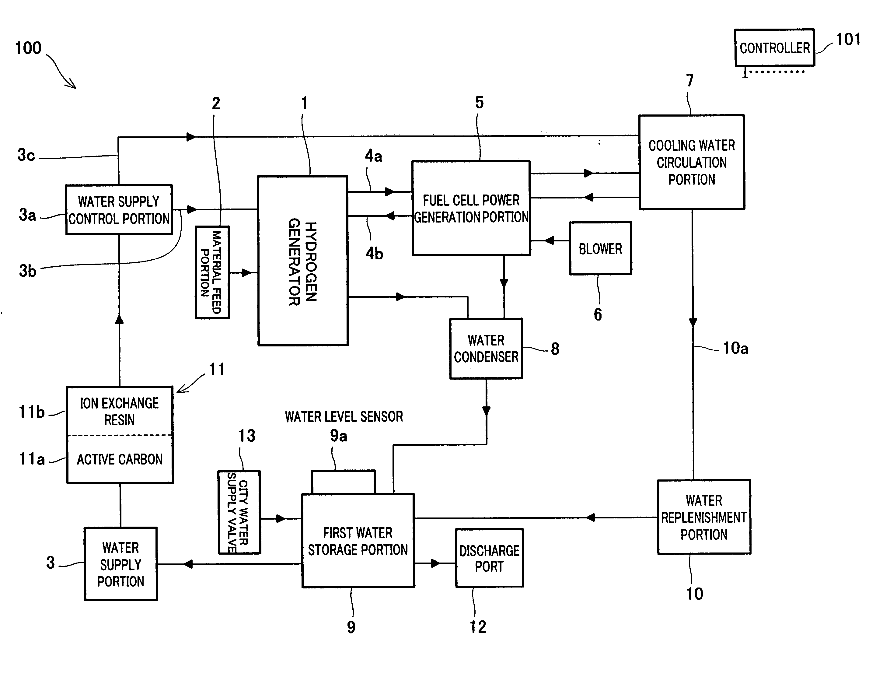
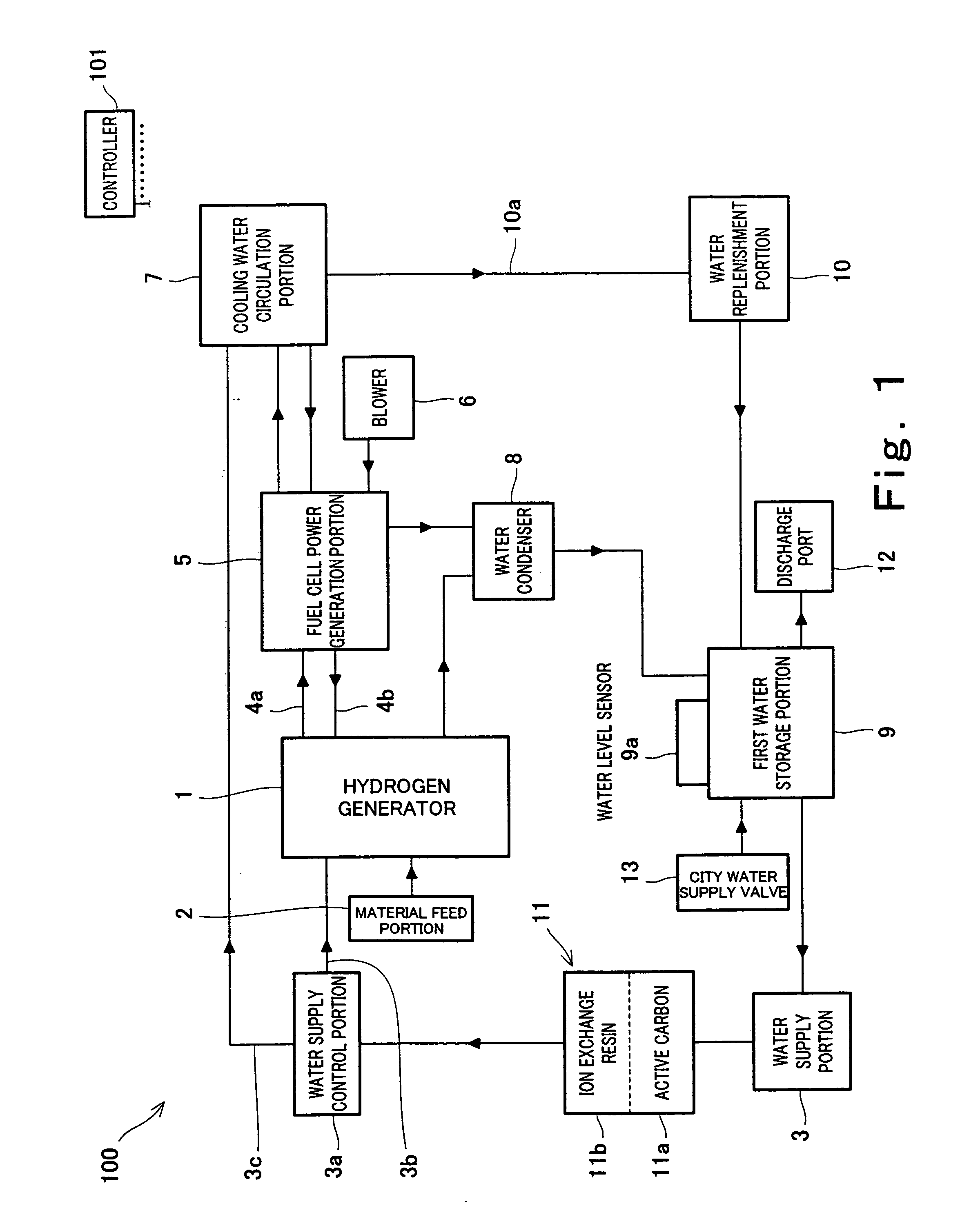
[0086]FIG. 1 is a block diagram schematically showing a construction of a fuel cell system according to an embodiment 1 of the present invention. In FIG. 1, solid lines between components of the fuel cell system indicate pipes, and arrows indicated on these solid lines indicate flow directions of water, a reformed gas, and so on, flowing in the pipes, in a normal state.

[0087] As shown in FIG. 1, a fuel cell system 100 of this embodiment includes a hydrogen generator 1. The hydrogen generator 1 is configured to cause a reforming reaction to mainly proceed using a material including an organic compound containing at least carbon and hydrogen, for example, a natural gas, a hydrocarbon component such as LPG, alcohol such as methanol, or a naphtha component, and steam to generate a hydrogen-rich reformed gas. The hydrogen generator 1 ...

embodiment 2

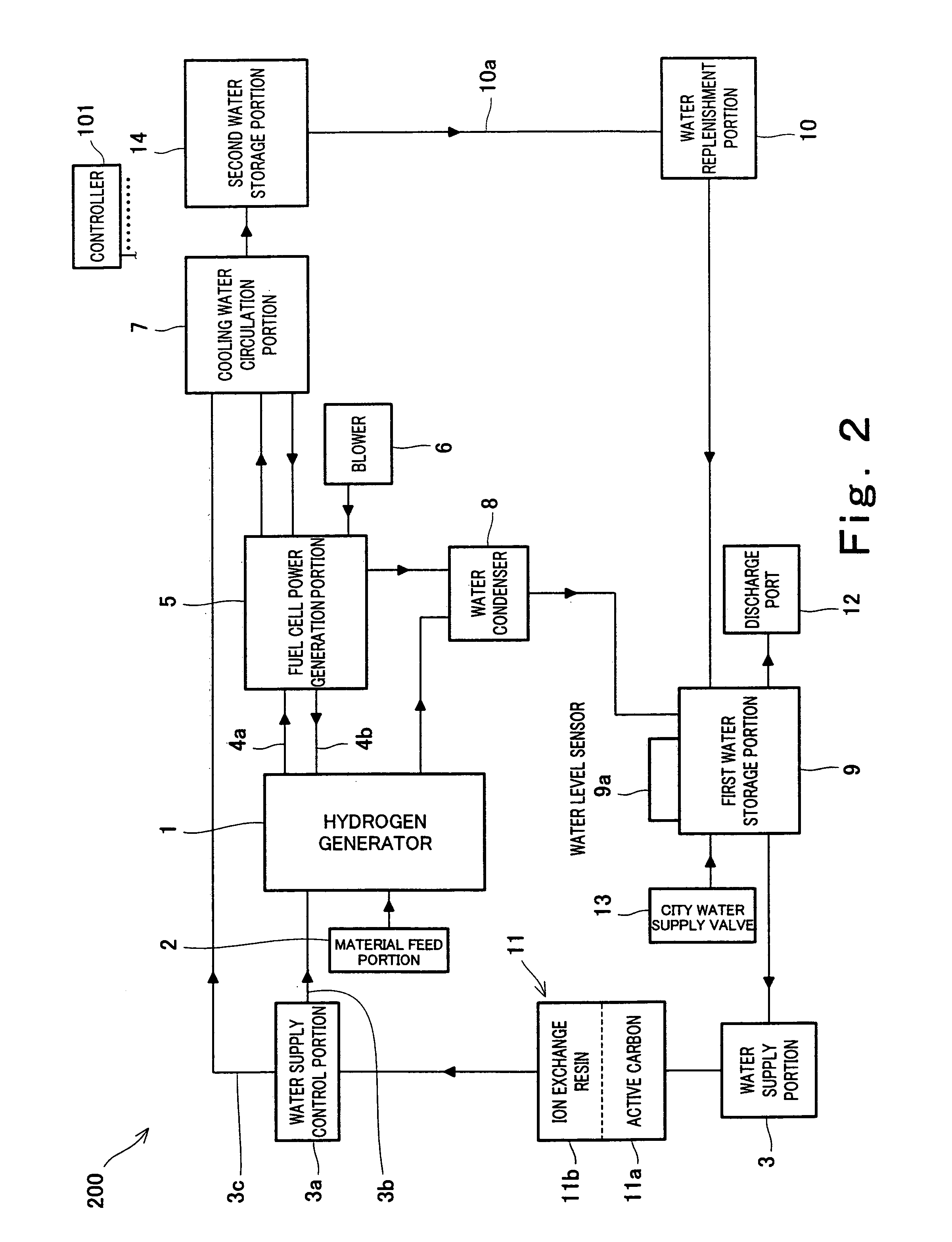
[0122]FIG. 2 is a block diagram schematically showing a construction of a fuel cell system according to an embodiment 2 of the present invention. In FIG. 2, solid lines extending between the components in the fuel cell system indicate pipes, and arrows on the solid lines indicate flow directions of water, a reformed gas, and so on, flowing in the pipes. In FIG. 2, the same components as those of the fuel cell system 100 of the embodiment 1 are identified by the same reference numerals.

[0123] As shown in FIG. 2, a fuel cell system 200 of this embodiment includes components substantially identical to those of the fuel cell system 100 of the embodiment 1. The construction of the fuel cell system 200 of this embodiment is identical to the construction of the fuel cell system 100 of this embodiment 1 except that a second water storage portion 14 is disposed at a location of the water replenishment passage 10a coupling the cooling water circulation portion 7 to the water replenishment po...

embodiment 3

[0128]FIG. 3 is a block diagram schematically showing a construction of a fuel cell system according to an embodiment 3 of the present invention. In FIG. 3, solid lines extending between the components in the fuel cell system indicate pipes, and arrows on the solid lines indicate flow directions of water, a reformed gas, and so on, flowing in the pipes. In FIG. 3, the same components as those of the fuel cell system 100 of the embodiment 1 are identified by the same reference numerals.

[0129] As shown in FIG. 3, a fuel cell system 300 of this embodiment includes components substantially identical to those of the fuel cell system 100 of the embodiment 1. The construction of the fuel cell system 300 of this embodiment is identical to that of the fuel cell system 100 of the embodiment 1 except that a cooler 15 is disposed at a location of the water replenishment passage 10a coupling the cooling water circulation portion 7 to the water replenishment portion 10, and a water temperature d...


PUM

PropertyMeasurementUnit
temperatureaaaaaaaaaa
temperaturesaaaaaaaaaa
temperatureaaaaaaaaaa

Abstract

A fuel cell system is provided, which is capable of effectively suppressing progress of decay of water with a simple configuration and without energy consumption so as not to substantially cause problems to occur in water supply and water purification functions. [Solving means] A fuel cell system includes a hydrogen generator (1) configured to generate hydrogen by causing a reforming reaction to proceed using a material and water, a fuel cell (5) configured to generate power by causing an electrochemical reaction to proceed using the hydrogen generated in the hydrogen generator and an oxidizing agent, a cooling water circulation portion (7) configured to circulate water for cooling the fuel cell, a water condenser (8) configured to condense water discharged from at least one of the hydrogen generator and the fuel cell, a first water storage portion (9) configured to store the water condensed by the water condenser, a water supply portion (3) configured to take out the water from the first water storage portion and to supply the water to at least one of the hydrogen generator, the fuel cell, and the cooling water circulation portion, a controller, and a water replenishment portion (10) configured to replenish water in the first water storage portion from the cooling water circulation portion, wherein the first water storage portion is provided with a discharge port; and the controller is configured to perform control so that the water in the first water storage portion is discarded through the discharge port and the water replenishment portion causes the cooling water circulation portion to replenish the water in the first water storage portion.

Description

TECHNICAL FIELD [0001] The present invention relates to a fuel cell system configured to generate power using an organic compound containing at least carbon and hydrogen, and water. More particularly, the present invention relates to a fuel cell system capable of effectively suppressing progress of decay of the water. BACKGROUND ART [0002] Since a fuel cell system capable of high-efficient and small-scale power generation is conventionally easily configured to use heat energy generated during power generation, it has been developed as a distributed power generation system that is able to achieve high energy utilization efficiency. [0003] The fuel cell system includes a fuel cell which is a power generation portion. In this fuel cell, hydrogen (hydrogen gas) is typically used as a fuel for power generation. However, at present, a hydrogen supply means required to generate power in the fuel cell is not equipped as infrastructure. So, a conventional fuel cell system is equipped with a ...

Claims


Application Information

Patent Timeline
Patent Type & Authority Applications(United States)
IPC IPC(8): H01M8/04H01M8/06
CPCH01M8/04029H01M8/04126H01M8/04141Y02E60/50H01M8/04291H01M8/0606H01M8/04156
Inventor UKAI, KUNIHIROKONDO, YUMI
Owner PANASONIC CORP
Why Eureka
Try Eureka