Choke device for an internal combustion engine intake system

Inactive Publication Date: 2007-07-19
FAB ITAL MAGNETI MARELLI SPA
View PDF5 Cites 0 Cited by
  • Summary
  • Abstract
  • Description
  • Claims
  • Application Information

AI Technical Summary

Benefits of technology

[0007] It is an object of the present invention to provide a choke device, for an internal combustion engine intake

Problems solved by technology

This solution, however, is relatively heavy, is relatively bulky (also on account of the electronics controlling the electric motor), and is only sufficiently, though not particula

Method used


Image

  • Choke device for an internal combustion engine intake system
  • Choke device for an internal combustion engine intake system
  • Choke device for an internal combustion engine intake system

Examples


Embodiment Construction

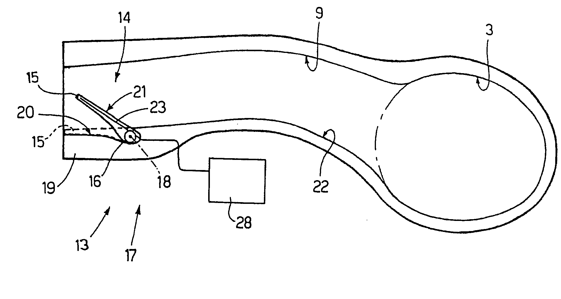
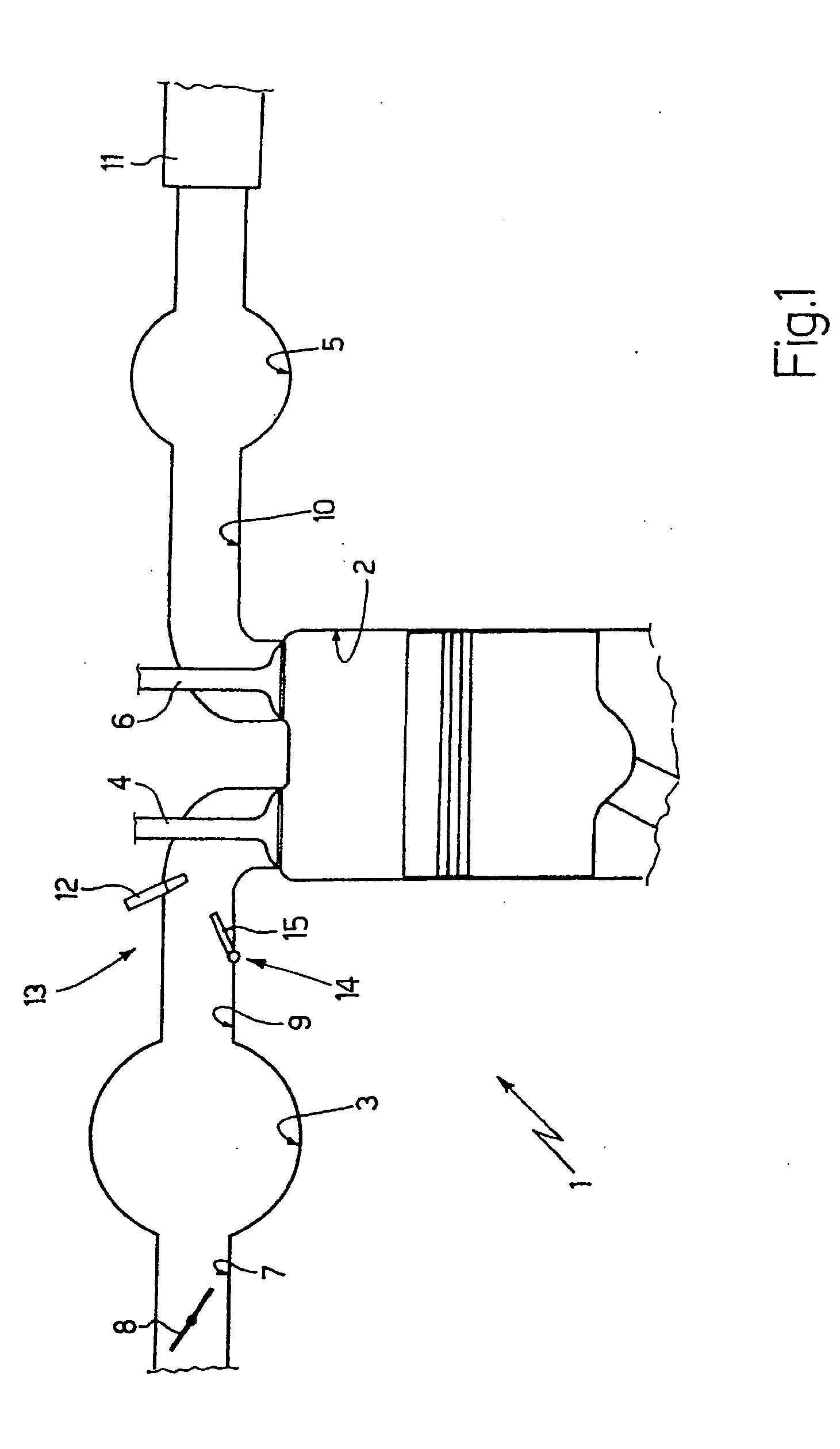
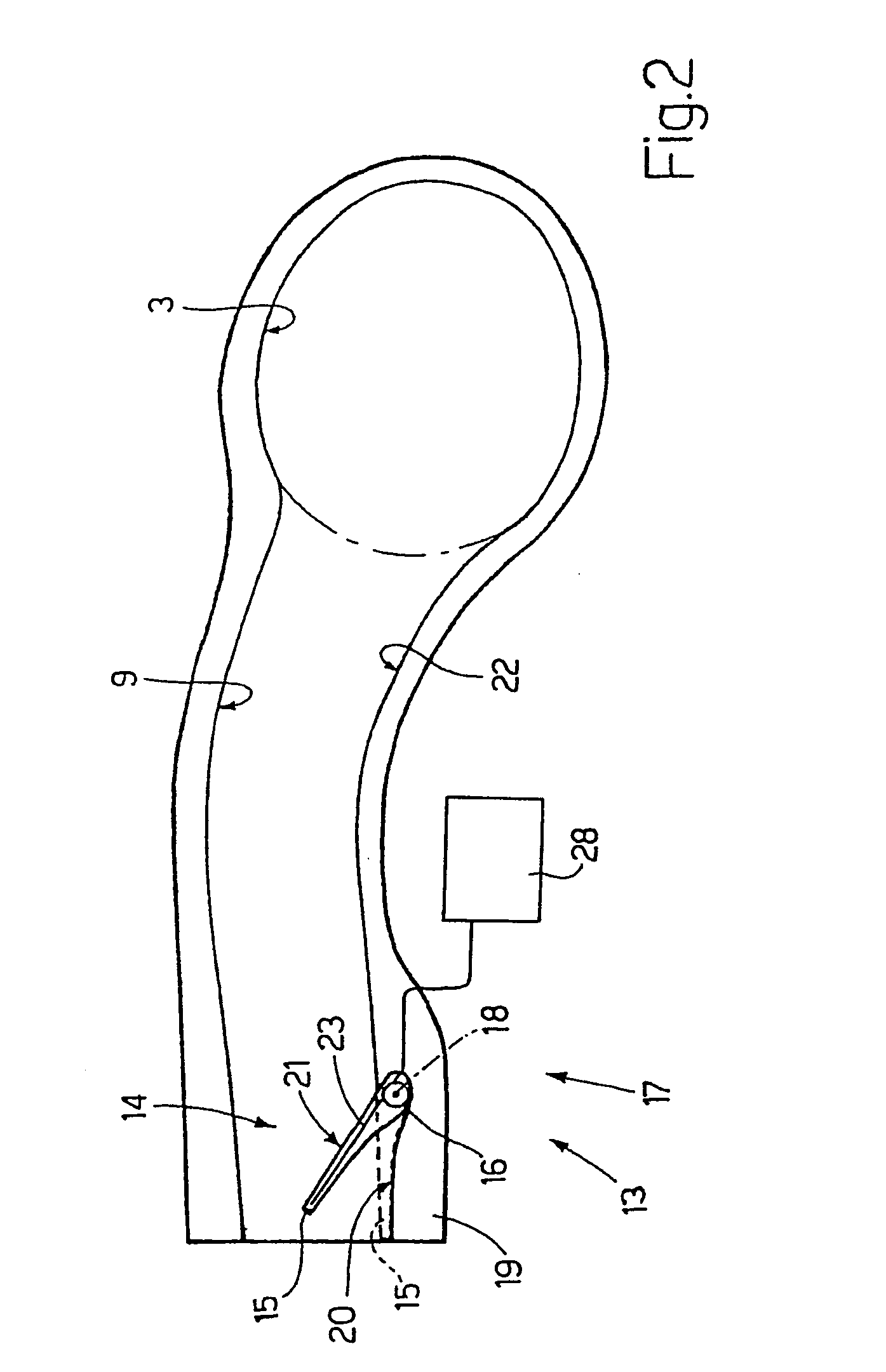
[0013] Number 1 in FIG. 1 indicates as a whole an internal combustion engine having four cylinders 2 (only one shown in FIG. 1), each of which is connected to an intake manifold 3 by at least one intake valve 4, and to an exhaust manifold 5 by at least one exhaust valve 6.

[0014] Intake manifold 3 is supplied with fresh air (i.e. from outside) by a feed conduit 7 regulated by a throttle valve 8, and is connected to cylinders 2 by respective intake conduits 9 (only one shown in FIG. 1), each of which is regulated by the corresponding intake valve 4. Similarly, exhaust manifold 5 is connected to cylinders 2 by respective exhaust conduits 10 (only one shown in FIG. 1), each of which is regulated by the corresponding exhaust valve 6; and an exhaust pipe 11 extends from exhaust manifold 5 and terminates with a known muffler (not shown) to expel combustion gases into the atmosphere.

[0015] In the embodiment shown, fuel (e.g. petrol, diesel fuel, methane, LPG, . . . ) is injected into each...


PUM


Abstract

A choke device for an intake system of an internal combustion engine; the choke device has at least one choke body fitted movably inside an intake conduit, and an actuating device for moving the choke body to and from a work position in which the choke body reduces the cross section of the intake conduit; and the actuating device has a filiform actuating member made of a shape-memory material that changes shape when subjected to physical external stress, and having a first portion embedded in the choke body, and a second portion located outside the choke body and secured mechanically to a fixed part.

Description

[0001] The present invention relates to a choke device for an internal combustion engine intake system. BACKGROUND OF THE INVENTION [0002] An internal combustion engine has a number of cylinders, each connected to an intake manifold by at least one intake valve, and to an exhaust manifold by at least one exhaust valve. The intake manifold is supplied with fresh air (i.e. from outside) by a feed conduit fitted with a throttle valve, and is connected to the cylinders by respective intake conduits, each terminating at least one intake valve. [0003] A choke device has recently been proposed to adjust the cross section of the intake conduits as a function of engine speed (i.e. drive shaft rotation speed). At low speed, the airflow section of the intake conduits is reduced to generate turbulence in the air intake and so improve mixing of the air and fuel in the cylinders, so that all the injected fuel is burnt, thus reducing combustion-generated pollutant emissions. At high speed, the air...

Claims


Application Information

Patent Timeline
IPC IPC(8): F02D9/10F02M1/00
CPCF01L3/205Y02T10/146F02D9/103F02B31/06Y02T10/12
Inventor BELLATO, NAZARIOSIRANI, SANDROCOLLI, MARCELLODRAGONI, EUGENIO
Owner FAB ITAL MAGNETI MARELLI SPA
Why Eureka
Try Eureka