Manipulation and cutting system and method

a cutting system and cutting technology, applied in the field of manipulating and cutting devices, can solve the problems of difficult to determine the precise depth of cut, difficult to cut efficiently, hidden edges or edges, etc., and achieve the effect of enhancing the efficiency of the blade element, and reducing the risk of injury

Inactive Publication Date: 2007-07-19
FLEX PARTNERS
View PDF7 Cites 35 Cited by
  • Summary
  • Abstract
  • Description
  • Claims
  • Application Information

AI Technical Summary

Benefits of technology

[0006] The present invention provides a means for rapid cutting of various materials including incision or dissection of tissues in a more controlled manner than currently exists. As an aspect of one exemplary embodiment of the invention, a blade and blade actuation mechanism is provided that allows for simultaneous rotation and advancement of a cutting edge. In one arrangement of the invention, the system of the present invention provides an appropriate blend of slicing and downward force in order to cut efficiently. In one exemplary arrangement, at least two such motions are combined when cutting, thereby enhancing the efficiency of a blade element in at least some applications.
[0007] Another aspect of the invention, present in at least some embodiments, is to optimize the efficiency of the cutting action by providing, for a cut along a straight path, linear motion along two of the three principal axes which beneficially affect cutting performance (slicing and downward forces) and in addition provide beneficial torque about the lateral axis, while minimizing motion and torque which is not beneficial, such as linear motion along the lateral axis or torque on the principal axes. It will be appreciated that, for a straight cut, linear motion relative to the longitudinal axis of the cutting element results in a slicing cut, and linear motion relative to the vertical axis results in a chopping or plunge cut. It will also be appreciated that a slicing motion is the result of torque.

Problems solved by technology

However, during certain procedures the sharp edge or edges may be hidden from view and prohibit the safe use of the cutting instrument.
Furthermore, as the edges are hidden, it is very difficult to determine the precise depth of cut.
Again, with these devices it is difficult to determine the precise depth of cut.
Excess energy delivered by these devices can result in collateral tissue damage, such as thermal charring and desiccation.

Method used


Image

  • Manipulation and cutting system and method
  • Manipulation and cutting system and method
  • Manipulation and cutting system and method

Examples


Embodiment Construction

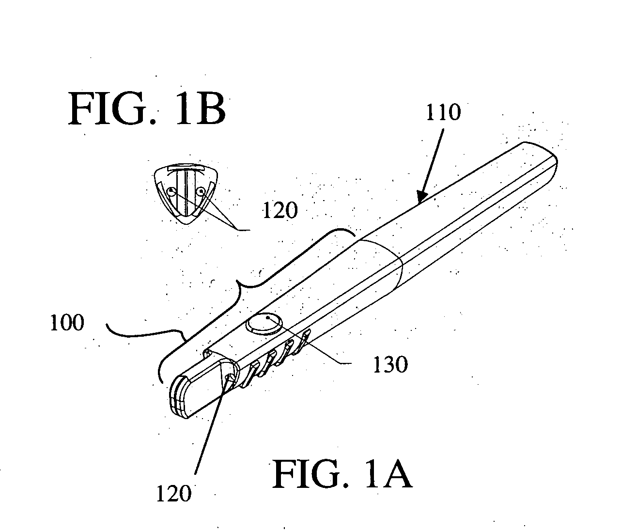
[0030] Referring first to FIGS. 1A and 1B, a cutting assembly 100 may be mounted at the distal tip of a pen like housing 110. The cutting assembly 100 may be used for cutting various materials. As one example, not intended to be a limitation, the cutting assembly can be used to cut commercially manufactured materials, such as paper or plastic, as well as organic material, such as animal or human tissue. The cutting assembly 100 can be made in a variety of shapes, but for the sake of clarity the cutting assembly 100 is shown to emulate the shape of a hand held cutting instrument, such as a scalpel. Furthermore, for the sake of clarity, the cutting assembly will be discussed or described herein in the context of cutting or manipulating organic tissue. However, the functional elements discussed and the methods set forth can easily be applied application relating to cutting manufactured materials, such as Kevlar or other fabrics.

[0031] Considered in the context of cutting animal or hum...


PUM


Abstract

A system for rapid manipulation and cutting that includes comprising a housing, a first cutting element, and a drive mechanism adapted to be mounted at least partly within the housing and connected to the first cutting element for imparting relative motion to the first cutting element as a combination of slicing and downward forces at the portion of the first cutting element which is adapted to contact the tissue.

Description

RELATED APPLICATION [0001] This application is related to provisional U.S. Patent Application Ser. No. 60 / 444,326, filed Jan. 31, 2003 and having the same inventors and same title as the present application, and which is incorporated herein by reference.FIELD OF THE INVENTION [0002] The present inventions relate to devices and techniques for manipulation and cutting, and more particularly relate to eccentric rotary mechanisms for the cutting and manipulation and methods therefore. BACKGROUND OF THE INVENTION [0003] A known cutting device is the rotary slicer. Where meat is advanced into a thin blade rotating at relatively high speeds. The cutting action of this device is defined by the high slicing to chopping ratio. The resultant blade velocity vector is nearly normal to the direction of advancement. Webb, U.S. Pat. No. 5,569,285 describes a hand powered circular rotary surgical blade with a concentrically mounted cylindrical depth guard. Mueller, U.S. Pat. No. 5507764, describes a...

Claims


Application Information

Patent Timeline
Patent Type & Authority Applications(United States)
IPC IPC(8): A61B17/32A61B17/00A61B18/14A61B19/00B26B25/00
CPCA61B17/32093A61B17/3211A61B18/1402B26B25/00A61B2017/00535A61B2017/320044A61B2019/306A61B2017/00367A61B2017/320028A61B2090/036
Inventor SIMPSON, PHILIP J.MATSUURA, DAVID G.GILLESPIE, WALTER DEAN
Owner FLEX PARTNERS
Why Eureka
Try Eureka