Intravascular deliverable stent for reinforcement of vascular abnormalities

a technology of vascular abnormalities and deliverable stents, which is applied in the field of deliverable stents or grafts, can solve the problems of low survival chances, too late, and not well suited for intravascular treatment of aaa

Inactive Publication Date: 2007-07-19
ST JUDE MEDICAL CARDILOGY DIV INC
View PDF41 Cites 265 Cited by
  • Summary
  • Abstract
  • Description
  • Claims
  • Application Information

AI Technical Summary

Benefits of technology

[0035]It is also desirable to have the braided layer ends progressively displaced toward the stent/graft center as one moves from the innermost tubular structure ends to the outer, further tubular structure ends. Assuming wire pitch in all layers is essentially the same, this makes the inner layer the longest, the middle layer a bit shorter and the outer layer the shortest in the construction of a three layer graft. This helps with eventual deployment in that it prevents the loose wire ends of the different layers from interacting and pr

Problems solved by technology

Once an AAA has ruptured, the chances of survival are low, with 80-90 percent of all ruptured aneurysms resulting in death.
AAA can be diagnosed from their symptoms when they occur, but this is often too late.
While the device in the '837 patent is altogether suitable for use as a coronary stent, it is not well suited for the intravascular treatment of AAA.
That device is of a uniform weave, but necessarily is of a wire density that is insufficient to limit the exposure of the aneurysm to aortic blood pressure.
Aneurysms may also occur in the thoracic aorta where the renal arteries are not involved in th

Method used


Image

  • Intravascular deliverable stent for reinforcement of vascular abnormalities
  • Intravascular deliverable stent for reinforcement of vascular abnormalities
  • Intravascular deliverable stent for reinforcement of vascular abnormalities

Examples


Embodiment Construction

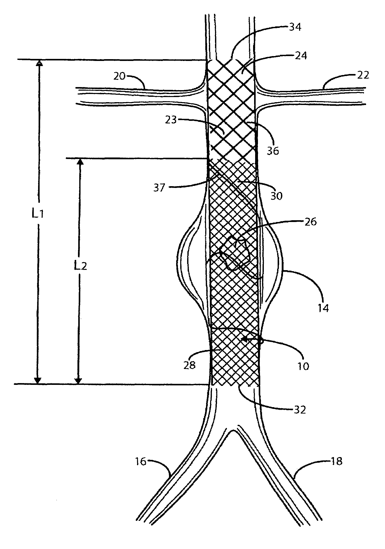
[0045]Referring to FIG. 1, there is indicated generally by numeral 10 the preferred embodiment of the stent / graft constructed in accordance with the present invention. The stent / graft 10 is shown in place in a segment of the abdominal aorta 12 having an aneurysm 14. At its lower end, the abdominal aorta 12 branches into the left and right common iliac arteries 16 and 18. Also shown in FIG. 1 are renal arteries 20 and 22 leading to the kidneys (not shown).

[0046]The stent / graft 10 comprises an innermost tubular structure 23 of a first length (L1) and at least one further tubular structure 26 of a length L2, both structures having a predetermined similar diameter. The stent / graft may have an overall length L1 in the range of 12 to 16 cm, preferably 14 cm. and a length L2 in the range of 8 to 12 cm, preferably 10 cm.

[0047]The innermost tubular structure comprises a first plurality of braided wire strands 24, preferably of a shape memory alloy, such as Nitinol. The braid comprising the i...


PUM


Abstract

A catheter deliverable stent/graft especially designed to be used in a minimally invasive surgical procedure for treating a variety of vascular conditions such as aneurysms, stenotic lesions and saphenous vein grafts, comprises an innermost tubular structure and at least one further tubular member in coaxial arrangement. In one embodiment, the innermost tubular structure is of a length (L1) and is formed by braiding a relatively few strands of highly elastic metallic alloy. The pick and pitch of the braid are such as to provide relative large fenestrations in the tubular wall that permit blood flow through the wall and provide the primary radial support structure. A portion of the innermost tubular structure of a length L1 is surrounded by a further braided tubular structure having relatively many strands that substantially inhibit blood flow through the fenestrations of the innermost tubular structure. The composite structure can be stretched to reduce the outer diameter of the stent/graft, allowing it to be drawn into a lumen of a delivery catheter. The catheter can then be advanced through the vascular system to the site of treatment and then released, allowing it to self-expand against the vessel wall. Various optional embodiments are disclosed that allow one skilled in the art to tailor the design to the specific application.

Description

CROSS-REFERENCE TO RELATED APPLICATION[0001]The present application is a continuation-in-part of co-pending application Ser. No. 11 / 331,640, filed on Jan. 13, 2006, the entirety of which is incorporated herein by reference for any purpose.BACKGROUND OF THE INVENTION[0002]I. Field of the Invention[0003]This invention relates generally to an intravascular deliverable stent or graft. In particular this invention relates to a unique stent or graft for the treatment of aneurysms, lesions, and saphenous vein grafts by reinforcing, excluding, bridging, or lining a blood vessel. Although emphasis is given to such a stent or graft specifically designed for addressing aneurysms and particularly iliac artery and abdominal aortic aneurysm (AAA), other embodiments suitable for saphenous vein graft (SVG), dialysis graft, and carotid arteries are also disclosed.[0004]II. Discussion of the Prior Art[0005]An aortic aneurysm is a weak area in the aorta, the main blood vessel that carries blood from t...

Claims


Application Information

Patent Timeline
IPC IPC(8): A61F2/06A61F2/90
CPCA61F2/07A61F2/90A61F2210/0014A61F2250/0015A61F2250/0023A61F2250/0037A61F2220/0075A61F2/82A61F2/852A61F2002/823A61F2210/0076A61F2220/0008A61F2220/0041A61F2002/075A61F2/86A61L27/04A61M25/01
Inventor AMPLATZ, KURTOSLUND, JOHN C.RUSSO, PATRICKGU, XIAOPING
Owner ST JUDE MEDICAL CARDILOGY DIV INC
Why Eureka
Try Eureka