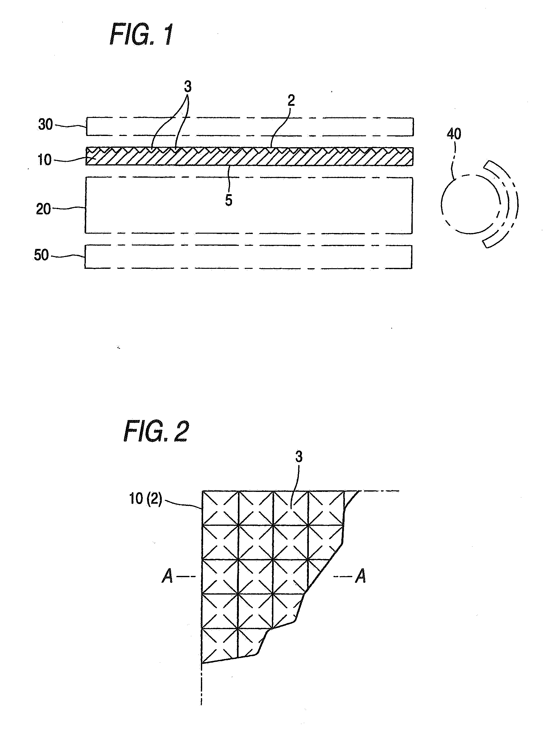
[0014] A light diffusing sheet in which fine recesses having a shape which is any of the shape of an inverted polyangular pyramid, the shape of an inverted truncated polyangular pyramid, the shape of an inverted cone, and the shape of an inverted truncated cone have been formed in at least one of the surfaces thereof as in the
first light diffusing sheet of the invention is free from the trouble that the surface having fine recesses mars a film, etc., because in this light diffusing sheet, the vertex parts of the recesses in the surface are connected in all directions and are flat. These fine recesses can be easily formed by
embossing. This light diffusing sheet can hence be continuously and efficiently produced by subjecting a sheet formed by
melt extrusion to embossing with an embossing roll or the like. In particular, in the case of forming recesses regularly arranged, embossing with a roll is easy and these recesses can be easily formed. Consequently, the
first light diffusing sheet of the invention is less apt to mar a lens film, etc., and attains
high productivity and a cost reduction as compared with the light diffusing film (sheet) disclosed in
patent document 1, which is produced one by one by injection molding or the like. In addition, the light diffusing sheet can be easily produced in a small thickness.
[0015] When the
first light diffusing sheet of the invention is disposed so that the surface thereof which has fine recesses formed therein serves as a
light emission side, then the light which has entered after having passed through the lightguide plate or having been emitted by the light source is converted to diffused light having a small brightness peak angle due to the light-refracting function of the inclined faces of the fine recesses having the shape of an inverted polyangular pyramid or inverted truncated polyangular pyramid or the light-refracting function of the tapered surfaces of the fine recesses having the shape of an inverted cone or inverted truncated cone, before being emitted and led to the lens film. Consequently, by bringing this diffused light having a small brightness peak angle to the front direction (the direction perpendicular to the screen of the liquid-
crystal display) by the lens film, the luminance of the screen of the liquid-
crystal display can be sufficiently heightened. In addition, since light is intensely diffused by the fine recesses, the dots on the lightguide plate and the bright lines attributable to the light source become less apt to be visually recognized. Namely, hiding properties are improved and the generation of a moiré or interference fringe is inhibited. In this case, when the light diffusing sheet contains a light diffusing agent, light is diffused more intensely to increase the
haze. Because of this, the hiding properties are improved further and the effect of inhibiting the generation of a moiré or interference fringe is also improved.
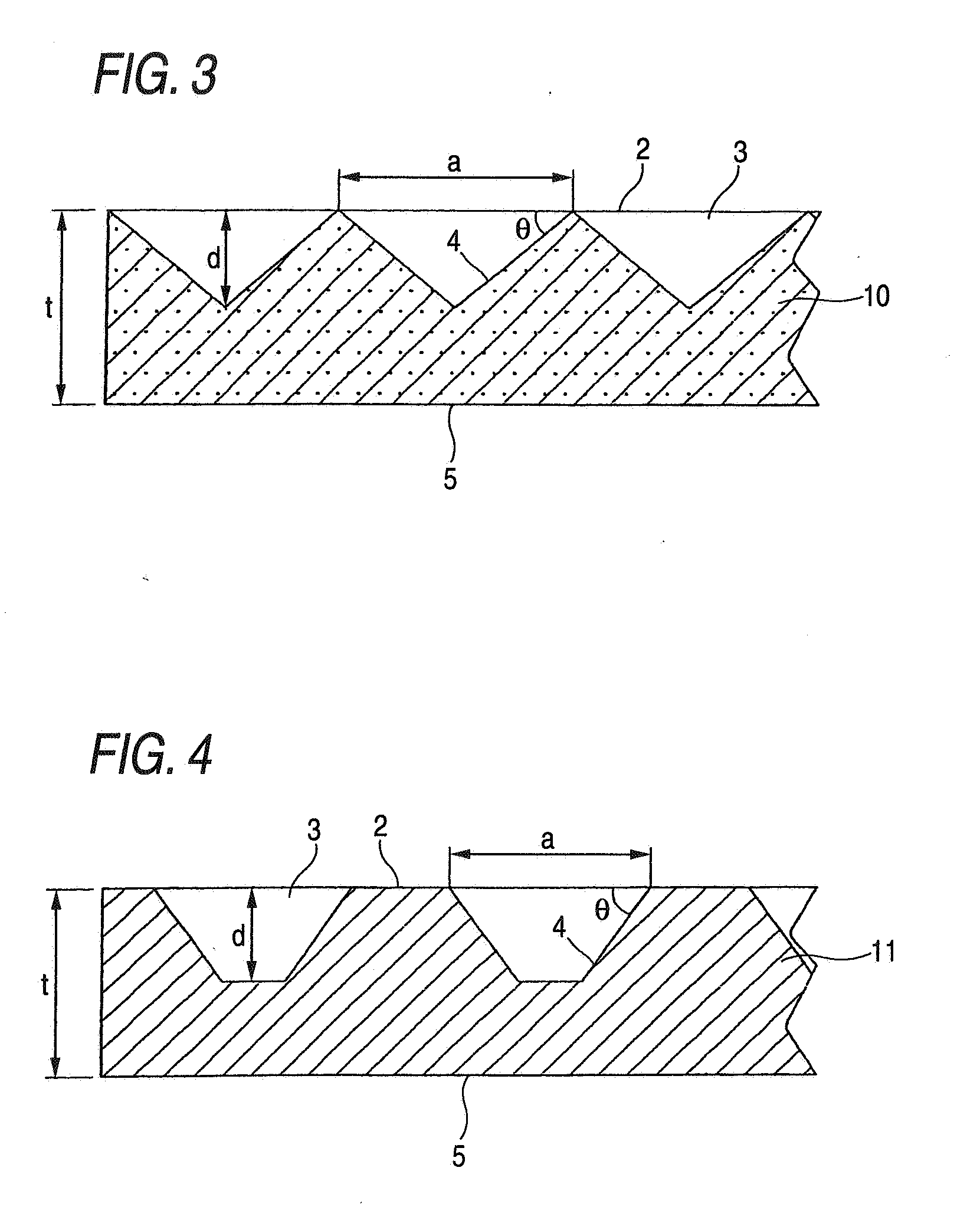
[0016] The function of reducing the brightness peak angle of the diffused light emitted from the light diffusing sheet is remarkable when the bevel between the surface having fine recesses formed (
light emission side) and each inclined face of each fine recess having the shape of an inverted polyangular pyramid or inverted truncated polyangular pyramid or the bevel between that surface and the ridgeline of each fine recess having the shape of an inverted cone or inverted truncated cone is 15-70° and when the proportion of the area occupied by the fine recesses in the surface having the fine recesses formed therein (light emission side) is 30-100%. Furthermore, when that bevel in the fine recesses is 35-70° and the areal proportion of the fine recesses is 30-100%, then the light which remained unemitted due to the total reflection of part of incident light and has been returned by a
light reflection sheet or the like and entered the light diffusing film again can be efficiently emitted. Because of this, luminance can be improved without reducing
haze.
[0017] Furthermore, the light diffusing sheet in which the fine recesses have been formed in an oblique-line arrangement is effective in making a moiré or interference fringe less visible and does not cause luminance unevenness.
[0009] The second light diffusing sheet of the invention comprises a core layer made of a light-transmitting resin and a
surface layer laminated to at least one of the surfaces of the core layer and made of a light-transmitting resin or of a light-transmitting resin containing a light diffusing agent, and is characterized in that the
surface layer has, formed in the surface thereof, fine recesses having a shape which is any of the shape of an inverted polyangular pyramid, the shape of an inverted truncated polyangular pyramid, the shape of an inverted cone, and the shape of an inverted truncated cone.
[0019] In the case where the surface
layers of the second light diffusing sheet are made of alight-transmitting resin containing no light diffusing agent, the following effect is brought about. Even when the core layer of this sheet contains a light diffusing agent, formation of this sheet by
melt extrusion molding (three-layer coextrusion molding) does not result in the so-called eye
mucus phenomenon in which the light diffusing agent adheres to the periphery of the
extrusion orifice, because the core layer is covered by the light-transmitting resin constituting the surface
layers. Consequently, the sheet surfaces can be prevented from bearing streak lines. On the other hand, in the case where the surface
layers contain a light diffusing agent, not only light diffusing properties are improved, but also the surface layers can have a reduced coefficient of linear expansion. Consequently, this light diffusing sheet can be prevented from rumpling, especially after the sheet is incorporated in a backlight unit and illuminated.
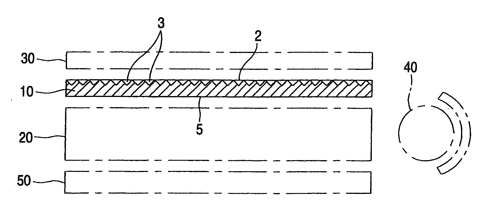
[0020] In the first and second light diffusing sheet of the invention in which the surface thereof on the side opposite to the surface having fine recesses formed has recesses and protrusions which are finer than the fine recesses, light
diffusion is further enhanced by these microfine recesses and protrusions and this further improves hiding properties. Furthermore, those in which a functional layer having light-transmitting properties, such as an
ultraviolet-absorbing layer or an antistatic layer, has been laminated to the surface on the side opposite to the surface having fine recesses formed have an
advantage that the function of the functional layer, such as, e.g., the prevention of deterioration by
ultraviolet or the prevention of dust
particle adhesion, is exhibited.
[0021] In the first backlight unit of the invention, the light which has passed through the lightguide plate and entered the light diffusing sheet of the invention having a thickness of 50-300 μm and which has a large brightness peak angle is brought to a direction where the brightness peak angle becomes small by the emission-side fine recesses having a shape which is any of the shape of an inverted polyangular pyramid, the shape of an inverted truncated polyangular pyramid, the shape of an inverted cone, and the shape of an inverted truncated cone. As a result, the light is emitted as diffused light having a small brightness peak angle. When a lens film has been disposed in front, the diffused light having a small brightness peak angle is led to the lens film and brought to the front direction by the lens film.
[0022] In the second backlight unit of the invention, the light which has been emitted by the light source and entered the light diffusing sheet of the invention having a thickness of 0.3-5 mm and which has a large brightness peak angle is likewise emitted after having been converted to diffused light having a small brightness peak angle by the emission-side fine recesses. When a lens film has been disposed in front, the diffused light is led to the lens film and brought to the front direction by the lens film.
[0023] Consequently, by incorporating these backlight units so as to be disposed on the back side of, e.g., the screen of a liquid-
crystal display, not only the luminance of the display screen is sufficiently heightened but also the dots on the back side of the lightguide plate and bright lines attributable to the light source are prevented from being visually recognized.

