Method and system for decoding multilevel signals

a multi-level signal and demodulation technology, applied in the field of optical fiber communication systems, can solve the problems of insufficient demodulation of multi-level signals, insufficient direct analog-to-digital conversion (adc) at a minimum number of bits, and inability to achieve multi-level signal demodulation advantages of conventional hardware and softwar

Inactive Publication Date: 2007-07-26
INTERSIL INC
View PDF99 Cites 38 Cited by
  • Summary
  • Abstract
  • Description
  • Claims
  • Application Information

AI Technical Summary

Benefits of technology

[0014] Unlike conventional optical receivers, the present invention can automatically control the thresholds or decision points for comparators of multilevel optical receivers that process multilevel data streams, where the noise corrupting the received signal is not necessarily Gaussian, signal independent, nor time-invariant. In other words, multilevel data streams can be distorted by noise where the noise follows a non-Gaussian probability distribution whose parameters depend on the transmitted signal values and vary with time. However, the present invention can still effectively process multilevel signals that have Gaussian, time-invariance, or signal-independence characteristics.
[0018] Instead of using the calculated pdf to determine an optimal set of thresholds, the CDF function itself in one exemplary embodiment can be used to determine the decision thresholds as it conveys the same information as the pdf but in a less intuitive form. In either case, the invention can assist with centering the voltage detection thresholds for each of the plurality of comparators. In the pdf exemplary embodiment, the invention can center the voltage detection thresholds at the troughs or local minima of the pdf (or equivalently at the points of inflection of the CDF) which correspond to near-optimal decision thresholds for the received signal. In this way, the probability of error in the detection of the individual symbols that make-up multilevel signal can be minimized.
[0024] A further aspect of the invention can include calculating the fidelity of a multilevel signal based upon an estimated marginal pdf. Specifically, the marginal pdf can be used to estimate a set of conditional pdfs (one for each candidate symbol of a multilevel signal). These conditional pdfs can then be used to estimate the probability of error for each symbol and hence the system as a whole. This aspect of the invention allows for error performance to be measured without explicit error tests that require testing sequences (known to the receiver) to be transmitted.

Problems solved by technology

While multilevel signals can offer this advantage of increased channel data throughput rates to an optical network architecture, conventional hardware and software used to decode the multilevel signal often cannot achieve this advantage because of difficulties in establishing thresholds by receivers for a multilevel signal.
The difficulties in establishing the thresholds are associated with reliably characterizing the noise that is present within a multilevel signal.
Further, conventional hardware and software do not address multilevel signals comprising greater than two-level data streams.
Since the troughs or “eyes” of a pdf are usually not uniformly distributed in voltage, a simple conventional direct analog-to-digital conversion (ADC) at a minimum number of bits is not adequate for decoding a multilevel signal.
However, the noise in optical channels of a multilevel signal may have distributions that are non-Gaussian.
Further, the distortion of multilevel signals may be nonlinear in nature resulting in asymmetric or multi-modal pdfs for the received signal.
In addition to the problems associated with estimating noise distributions in a multilevel signal, another problem exists in the conventional art with respect to reliably determining the fidelity of a received multilevel signal without the explicit transmission of a “testing” data sequence that is already known to the receiver.
When the detected sample from this second threshold differs from the primary sample, a pseudo-error is said to have occurred.
This class of approaches, however, neglects the fact that under optimal filtering, the primary and secondary samples will be heavily statistically correlated, and thus, misrepresents the link performance.
This class of performance monitors, however, suffers two significant drawbacks.
First, these methods require the use of an error correction code so that errors can be detected.
The second drawback is that transmission errors must occur in order to acquire statistics regarding their frequency of occurrence.
By the very nature of the high quality of the link, these errors will rarely occur, and thus, the performance monitor requires a significant amount of time to reliably report the error rate.

Method used


Image

  • Method and system for decoding multilevel signals
  • Method and system for decoding multilevel signals
  • Method and system for decoding multilevel signals

Examples


Embodiment Construction

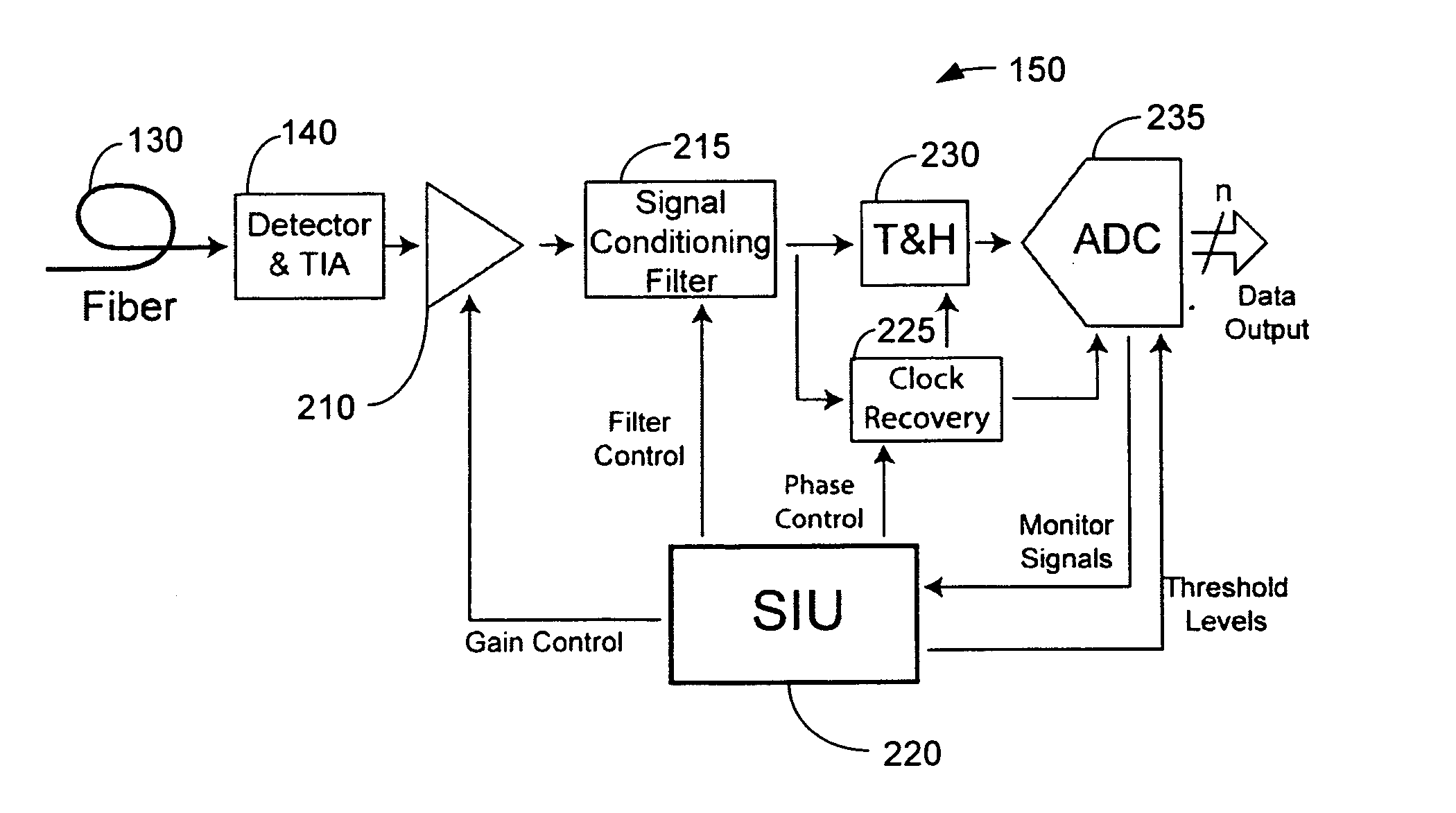
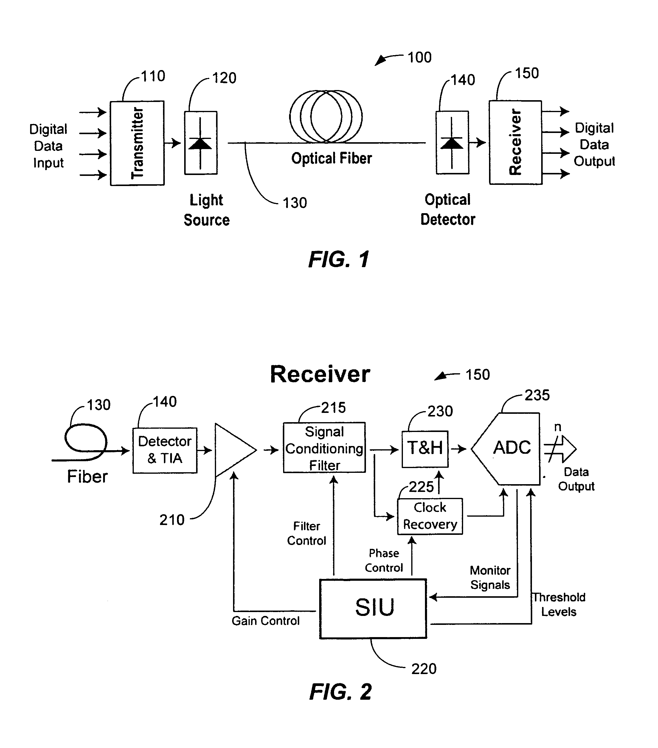
[0051] The present invention can select a near-optimal set of decision thresholds that can be used by an optical receiver in order to decode a multilevel optical signal. The multilevel optical receiver can comprise a plurality of comparators that generally correspond with the number of levels in a multilevel data stream. Each comparator can be individually controlled and fed a decision threshold in order to decode a particular symbol from a multilevel signal. Alternatively, a high-resolution analog-to-digital converter (ADC) can measure the voltage of the received multilevel signal. The digitized multilevel signal can be provided to a digital signal processor (DSP) which computes the pdf and decision thresholds. The DSP can then use the computed thresholds to decode subsequent digitized symbols from the multilevel signal.

[0052] The present invention typically does not require the assumption of Gaussianity, time-invariance, signal-independence, or binary signaling. Contrary to the c...


PUM


Abstract

A multilevel optical receiver can comprise a plurality of comparators that generally correspond with the number of levels in a multilevel data stream. Each comparator can be individually controlled and fed a decision threshold in order to decode a multilevel signal. The multilevel optical receiver can generate a statistical characterization of the received symbols in the form of a marginal cumulative distribution function (CDF) or probability density function (pdf). This characterization can be used to produce a set of ε-support estimates from which conditional pdfs are derived for each of the transmission symbols. These conditional pdfs may then be used to determine decision thresholds for decoding the received signal. The conditional pdfs may further be used to continuously estimate the fidelity or error rate of the received signal without the transmission of a testing sequence. The ε-supports may further be used to automatically control the gain on the receiver.

Description

CROSS REFERENCE TO RELATED APPLICATIONS [0001] The present application claims priority under 35 U.S.C. § 119(e) to U.S. Provisional Application Ser. No. 60 / 281,526 entitled, “Automatic Threshold Tracking and Digitization Method for Multilevel Signals,” filed on Apr. 4, 2001 in the name of Hietala et al. The entire contents of which are hereby incorporated by reference. This application is also related to U.S. Non-provisional application Ser. No. 10 / 032,586 entitled, “Increasing Data Throughput in Optical Fiber Transmission Systems,” filed on Dec. 21, 2001.FIELD OF THE INVENTION [0002] The present invention relates to optical fiber communication systems and increasing the throughput of data transmission over an optical fiber communication system through the use of multilevel modulation. Specifically, the present invention relates to a method and system for demodulating multilevel signals. BACKGROUND OF THE INVENTION [0003] The use of multilevel signals in an optical network architect...

Claims


Application Information

Patent Timeline
Patent Type & Authority Applications(United States)
IPC IPC(8): H04L25/06H04L1/00H04L25/03H04L25/34H04L27/02H04L27/36
CPCH04L1/004H04L27/367H04L27/02H04L25/03343
Inventor HIETALA, VINCENT MARKKIM, ANDREW JOO
Owner INTERSIL INC
Why Eureka
Try Eureka