Copper grid repair technique for lightning strike protection

a copper grid and repair technique technology, applied in the field of copper grid repair technique, can solve the problems of increasing the potential difference produced across the ply structure, no readily available electrically conductive path for discharging current, arcing and dangerous sparks, etc., to maintain the integrity of the lightning prevention system, quick and cost-effective repairs, and reduce resistance paths

Active Publication Date: 2007-08-02
THE BOEING CO
View PDF10 Cites 58 Cited by
  • Summary
  • Abstract
  • Description
  • Claims
  • Application Information

AI Technical Summary

Benefits of technology

[0013] The techniques of the preferred embodiments described above are relatively simple and available to make quick and cost-effective repairs to commercial aircraft already in service. This repair helps to maintain the integrity of the lightning prevention system to help divert lightning currents away from the fuel tank substructures by providing a lower resistance path along the wing's surface. The repair also maintains the reduction of current density at the target fasteners by allowing current sharing to the neighboring fasteners due to the reduced parallel path resistance created by the copper foil. The repairs allow the commercial aircraft to be placed back in service quickly and at a minimum of time and expense.

Problems solved by technology

In a carbon fiber composite structure, which is approximately 2000 times more resistive than aluminum, the carbon fiber plies act as very high resistance conductors and the resin between the plies acts as highly capacitive dielectric layers so that lightning striking the carbon fiber composite results in an increasing potential difference produced across the ply structure but no readily available electrically conductive path for discharging the current.
When the lightning energy is unable to dissipate at a fast enough rate, arcing and dangerous sparks are likely to occur.
This is a considerable problem, especially when the substructure is the wall of a fuel tank and arcing carries the highly dangerous risk of ejecting sparks, molten material and hot gasses into the fuel tank.
The problem with flame spraying or plating is that they are secondary operations used to apply the conductive layer to the already assembled structure.
In addition, it is difficult to achieve a satisfactory electrical bond using either of these processes.
The protective conductive layer also adds mass without contributing to the strength of the assembled structure, is vulnerable to environmental damage, and is difficult to maintain.
The production and maintenance of such an arrangement is thus clearly expensive.
However, the use of woven screens or foils requires the use of an additional ply of fiberglass when the non-metallic structure is carbon to electrically isolate the carbon layer from the metal to prevent corrosion that also adds non-structural weight.
Again, this approach to the problem of arcing is expensive because of the need for special fastener designs.
While the Pridham disclosure effectively protects the fuel system from lightning strikes, the proposed system does not address the need for repairing the copper grid system after a lightning strike or after other mechanical damage.

Method used


Image

  • Copper grid repair technique for lightning strike protection
  • Copper grid repair technique for lightning strike protection
  • Copper grid repair technique for lightning strike protection

Examples


Embodiment Construction

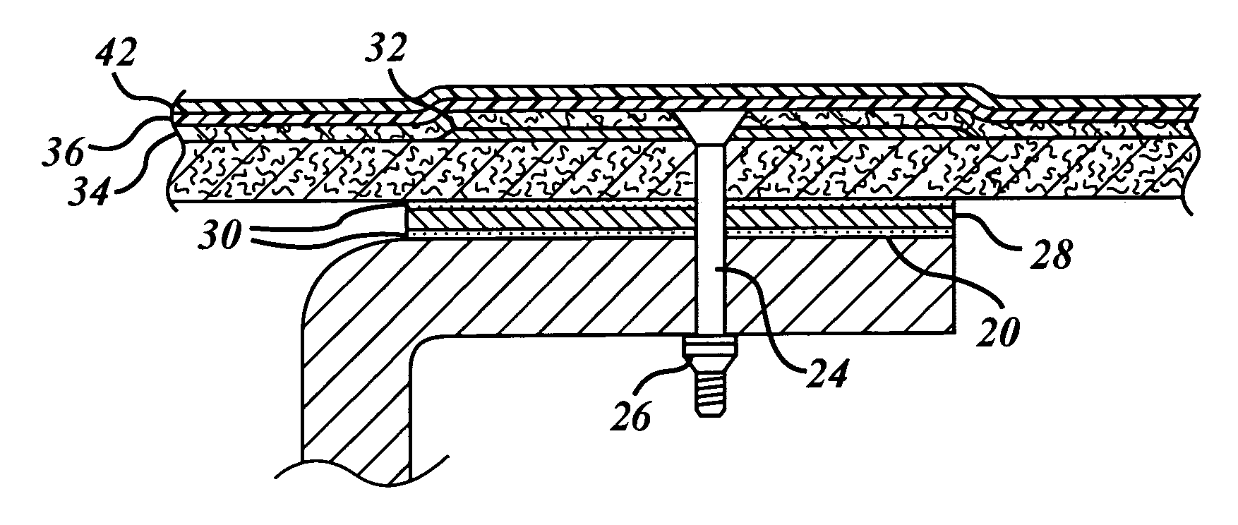
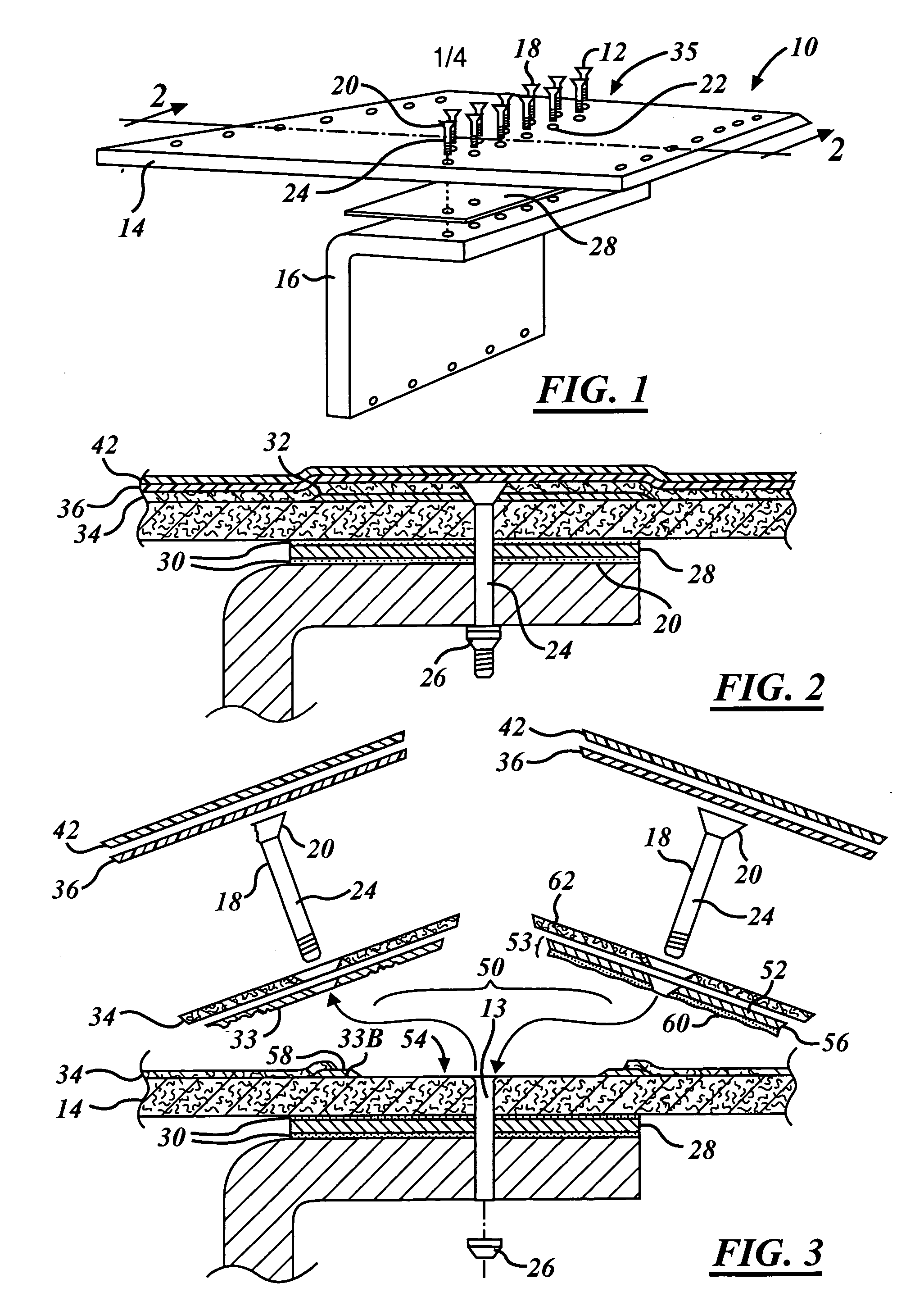
[0022] Referring now to FIGS. 1 and 2, a section and perspective view of a portion of a wing structure 10 of a commercial airplane showing a plurality of fasteners 12 is shown securing a skin panel 14 of an aircraft structure to an inner substructure 16, or spar 16, comprising the wall of a fuel tank.

[0023] The skin panel 14 and the spar 16 are made of carbon fiber composite material of low weight and high strength and stiffness formed by conventional methods well known in the art. For example, in one preferred form, the skin panel 14 is formed from 34 plies of an aircraft quality, machine lay-up structural carbon fiber / epoxy tape laid in a 50 / 40 / 10 orientation and having an overall thickness approximately 0.2516 inches, while the spar 16 consists of 44 plies of a hand lay-up version of aircraft quality, structural carbon fiber / epoxy tape laid in a 25 / 50 / 25 layup and having an overall thickness of about 0.3256 inches. Both the skin panel 14 and spar 16 are primed on both the tool a...


PUM

PropertyMeasurementUnit
temperatureaaaaaaaaaa

Abstract

A method for reestablishing the electrical continuity of an electrically conductive layer of a composite aircraft wing damaged by a lightning strike or other mechanical event is disclosed in which a copper patch replaced the damaged section of the electrically conductive layer contained. The repair is performed by first removing any surfacers, fasteners, and damaged electrically conductive layer to expose a portion of the underlying composite skin. A copper patch having a copper foil section coupled to an unsupported film adhesive is then introduced onto an underlying composite skin opening contained within an undamaged section of a copper foil grid and covered with resin-impregnated fiberglass material. The film adhesive and resin-impregnated fiberglass material are then cured and fasteners are then reinserted within the fiberglass material, copper patch and underlying composite skin. The surface of the composite wing is then reprimed and repainted to complete the repair.

Description

TECHNICAL FIELD [0001] The present invention generally relates to aircraft lightning protection techniques and more specifically to a copper grid repair technique for composite aircraft skin panels. BACKGROUND ART [0002] The use of carbon fiber reinforced plastic (“CFRP”) materials, otherwise known as carbon fiber composites, for structural members is increasing in commercial airplanes because of the higher strength-to-weight and stiffness-to-weight ratios afforded by carbon fiber composites as compared to traditional aluminum structures. [0003] A lightning strike to an aircraft causes a high electric current, which may typically be of the order of 100,000 amps, to flow through the aircraft frame. In a carbon fiber composite structure, which is approximately 2000 times more resistive than aluminum, the carbon fiber plies act as very high resistance conductors and the resin between the plies acts as highly capacitive dielectric layers so that lightning striking the carbon fiber compo...

Claims


Application Information

Patent Timeline
Patent Type & Authority Applications(United States)
IPC IPC(8): H01H47/00
CPCB29C73/10B64F5/0081B64D45/02B29L2031/3085B64F5/40
Inventor ACKERMAN, PATRICE K.BLANCHARD, STEVEN D.KOVACH, DANIEL J.
Owner THE BOEING CO
Why Eureka
Try Eureka