Fluid bearing device and manufacturing method thereof

a technology of fluid bearings and bearings, which is applied in the direction of elastic bearings, bearing units, rigid supports of bearing units, etc., can solve the problems of unsatisfactory oil repellent effect, unattainable mold precision for housings, and inferior repellency on mechanically processed resin surfaces to that observed on molded surfaces, etc., to achieve efficient assembly process, reduce manufacturing costs, and reduce the effect of housing manufacturing costs

Inactive Publication Date: 2007-08-02
NTN CORP +1
View PDF6 Cites 19 Cited by
  • Summary
  • Abstract
  • Description
  • Claims
  • Application Information

AI Technical Summary

Benefits of technology

[0025] According to the present invention, a fluid bearing device can be provided which enables a reduction in the manufacturing costs of the housing, and also enables a more efficient assembly process, thereby offering even lower costs.
[0026] Furthermore, according to the present invention, the molding precision of a housing produced by resin injection molding can be improved.
[0027] In addition, according to the present invention, the problem of a reduction in oil repellency at the gate removal portion of a housing produced by resin injection molding can be resolved.

Problems solved by technology

However, depending on the configuration of the injection molding, and particularly on the shape and position of the gate through which the molten resin is injected into the internal cavity, the required molding precision for the housing may not be achievable.
Furthermore, the gate removal portion, which is formed by removal (by mechanical processing) of a resin gate portion that is produced following the injection molding process, is formed at the surface where oil repellency is required, and even if an oil repellent is applied to this surface, a satisfactory oil repellent effect may still be unattainable.
Typically, the oil repellency of an oil repellent is significantly affected by the surface state of the base material to which it is applied, and the oil repellency on a mechanically processed resin surface is inferior to that observed on a molded surface.
However, in the molding method described above, a gate removal portion formed by removing the resin gate portion 7d′ is formed at the inner peripheral area of the outside surface 7a2′ regardless of whether the removal process is conducted along the line X or the line Y, and as a result, even if an oil repellent is applied to the outside surface 7a2′, a satisfactory level of oil repellency is often unattainable.

Method used


Image

  • Fluid bearing device and manufacturing method thereof
  • Fluid bearing device and manufacturing method thereof
  • Fluid bearing device and manufacturing method thereof

Examples


Embodiment Construction

[0032] As follows is a description of embodiments of the present invention.

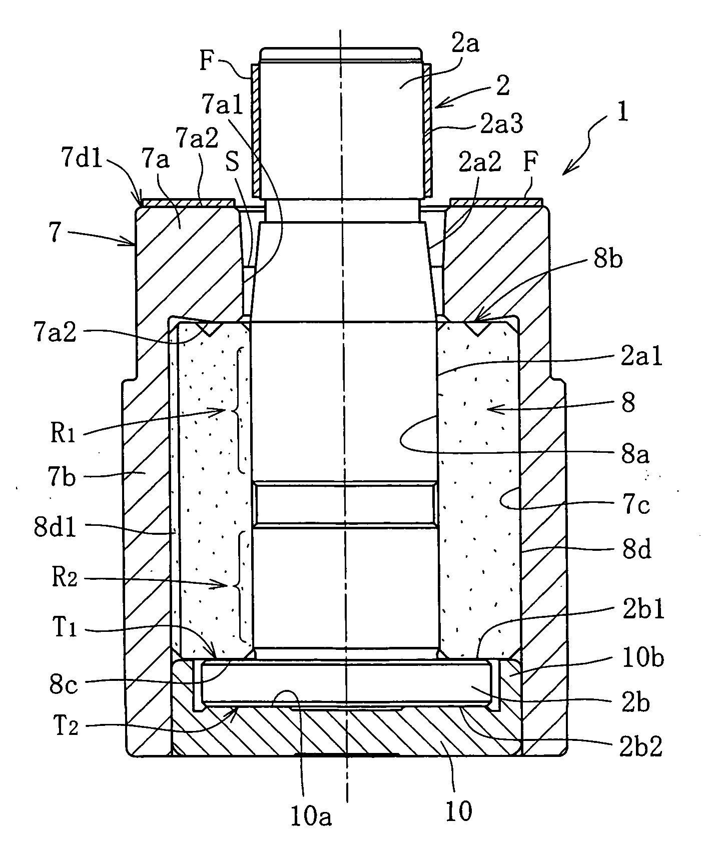
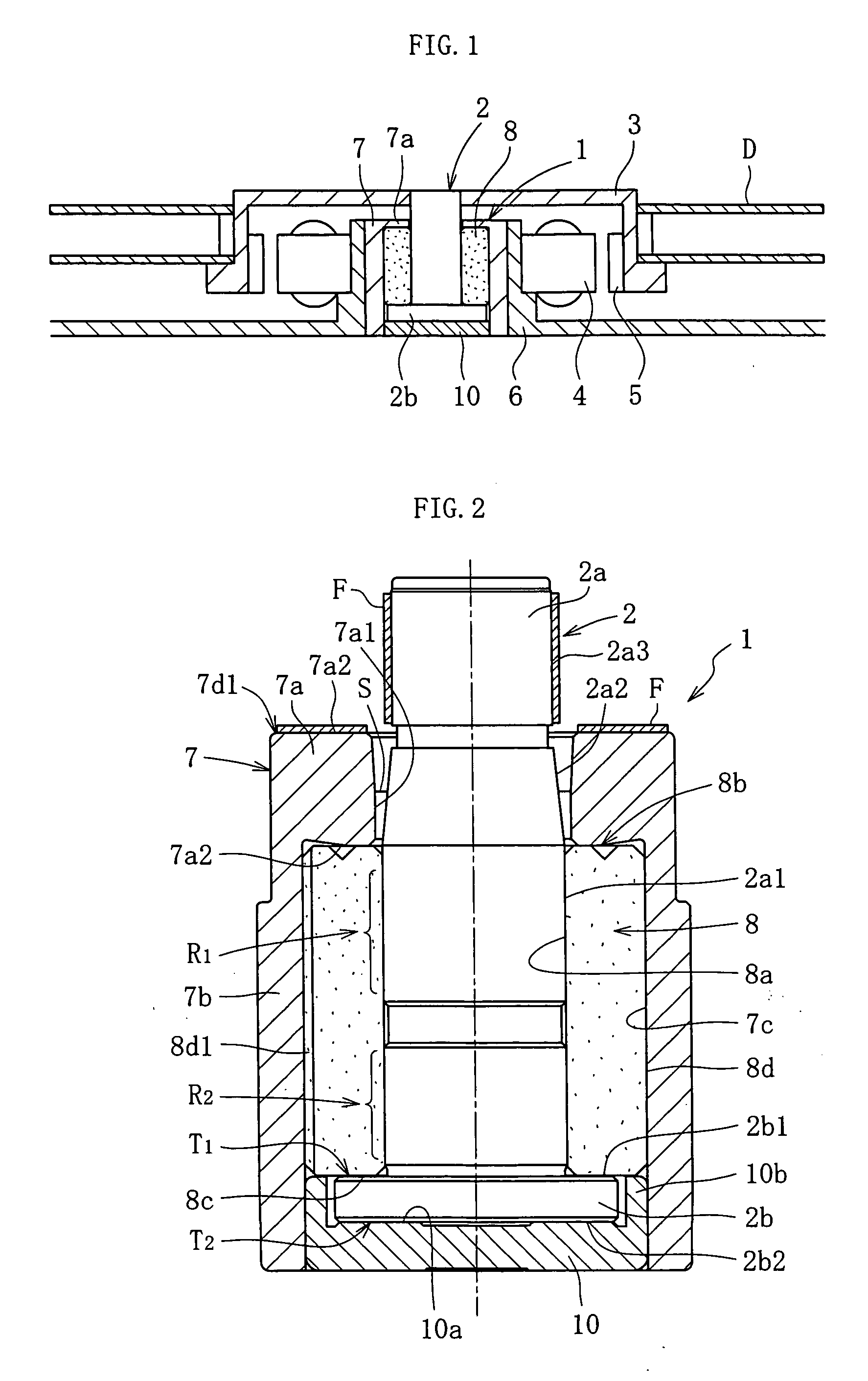
[0033]FIG. 1 is a schematic illustration showing one possible construction of a spindle motor for information-processing equipment incorporating a fluid bearing device (a fluid dynamic bearing device) 1 according to this embodiment. This spindle motor is used in a disk drive device for HDD or the like, and comprises a fluid bearing device 1 which supports a shaft member 2 in a freely rotatable, non-contact manner, a rotor (disk hub) 3 which is mounted onto the shaft member 2, and a stator 4 and a rotor magnet 5 which oppose one another across a gap in the radial direction, for example. The stator 4 is attached to the outer periphery of a bracket 6, and the rotor magnet 5 is attached to the inner periphery of the disk hub 3. A housing 7 for the fluid bearing device 1 is mounted to the inner periphery of the bracket 6. Either one disk or a plurality of disks D such as magnetic disks are supported by the disk h...


PUM

PropertyMeasurementUnit
diameteraaaaaaaaaa
widthaaaaaaaaaa
speedaaaaaaaaaa

Abstract

A molten resin P is filled into a cavity 17 through a film gate 17a provided a ring shape in a position corresponding with an outer peripheral edge of the outside surface 7a2 of the seal portion 7a. The molded product removed from the molding die is completed by removing the residual resin gate portion 7d. A gate removal portion 7d1 formed by removing the resin gate portion appears as a narrow ring shape at the outer peripheral edge of the outside surface 7a2 of the seal portion 7a.

Description

TECHNICAL FIELD [0001] The present invention relates to a fluid bearing device which supports a rotating member in a non-contact manner via a lubricating oil film that is generated within a radial bearing gap, as well as a method of manufacturing such a fluid bearing device. This bearing device is ideal for use in information-processing equipment, including the spindle motors for magnetic disk devices such as HDD and FDD, optical disk devices for CD-ROM, CD-R / RW, DVD-ROM / RAM, etc. and magneto-optical disk devices for MD, MO, etc., the polygon scanner motors in laser beam printers (LBP), or as small-scale motors for electrical equipment such as axial flow fans. BACKGROUND ART [0002] In each of the motor types described above, in addition to high rotational precision, other sought after performance factors include increased speed, lower costs, and lower noise generation. One of the structural elements that determines the performance of the motor in terms of these factors is the bearin...

Claims


Application Information

Patent Timeline
Patent Type & Authority Applications(United States)
IPC IPC(8): H02K5/16F16C32/06B29C45/26F16C17/02F16C17/10F16C27/00F16C33/74F16C35/02G11B19/20
CPCB29C45/261F16C17/02F16C2370/12F16C33/74G11B19/2018F16C17/10
Inventor SHIBAHARA, KATSUO
Owner NTN CORP
Why Eureka
Try Eureka