Process and plant for conversion of waste material to liquid fuel

a technology of liquid hydrocarbons and waste materials, applied in the field of plastic processing, can solve the problems of inability to recycle waste polymers as fuel, the tonnage of waste commodity plastics, or polymers, is improperly disposed of each year, and the abandonment of many recycling efforts

Active Publication Date: 2007-08-02
FUTURE ENERGY INVESTMENTS PTY LTD
View PDF7 Cites 85 Cited by
  • Summary
  • Abstract
  • Description
  • Claims
  • Application Information

AI Technical Summary

Benefits of technology

[0013] The present invention provides a process for the thermocatalytic conversion of waste materials into reusable fuels, comprising the steps of delivering waste material to a melting means; directing melted waste material from one or more manifolds into one or more pyrolysis chambers heating waste material to effect pyrolysis of material into a gaseous state in a substantia

Problems solved by technology

A considerable tonnage of waste commodity plastics, or polymers, are improperly disposed of each year.
However, the recycling and reuse of waste polymers, as now practiced without subsidies have proven to be uneconomic, forcing the abandonment of many recycling efforts.
The recycling of waste polymers as fuel has also not proven practical because of the inability to collect sufficient quantities to sustain operation of the recycling machinery.
Existing thermolysis system based plants are in operation but display a series of significant shortfalls and disadvantages, which ultimately result in inefficient production and throughput of liquid hydrocarbons from waste plastic materials.
A primary disadvantage is the process of loading plastic waste manually, and also the system being unable to receive variable sizes of plastic waste feedstocks.
The inability to fill the pyrolysis chamber to its maximum reduces the speed of the entire process and ultimately the throughput of these known thermolysis systems.
Of particular issue with the set up of existing pyrolysis chambers is that fuel may

Method used


Image

  • Process and plant for conversion of waste material to liquid fuel
  • Process and plant for conversion of waste material to liquid fuel
  • Process and plant for conversion of waste material to liquid fuel

Examples


Embodiment Construction

[0078] Unless defined otherwise in this specification, all technical tears are used herein according to their conventional definitions as they are commonly used and understood by those of ordinary skill in the art.

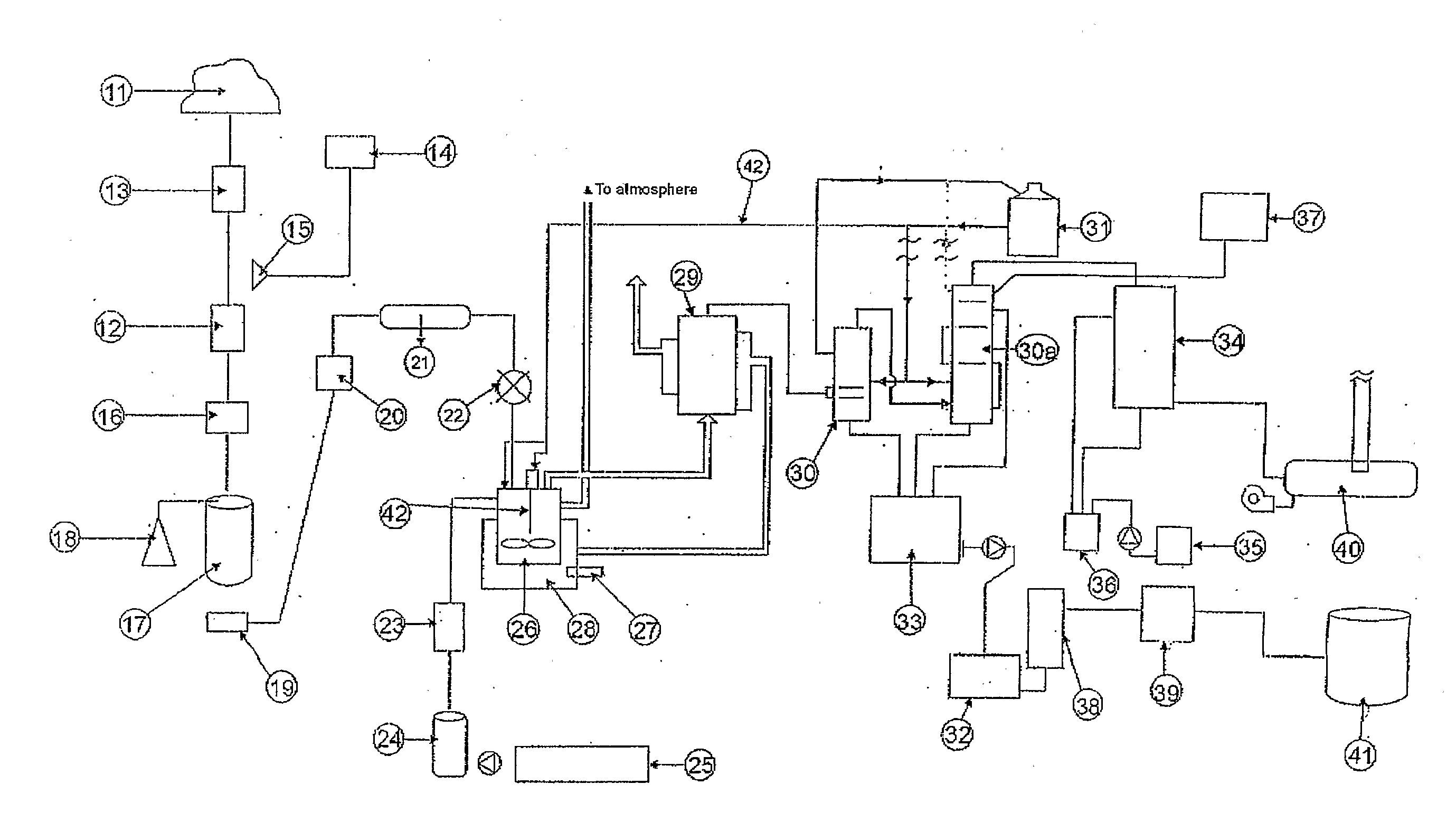
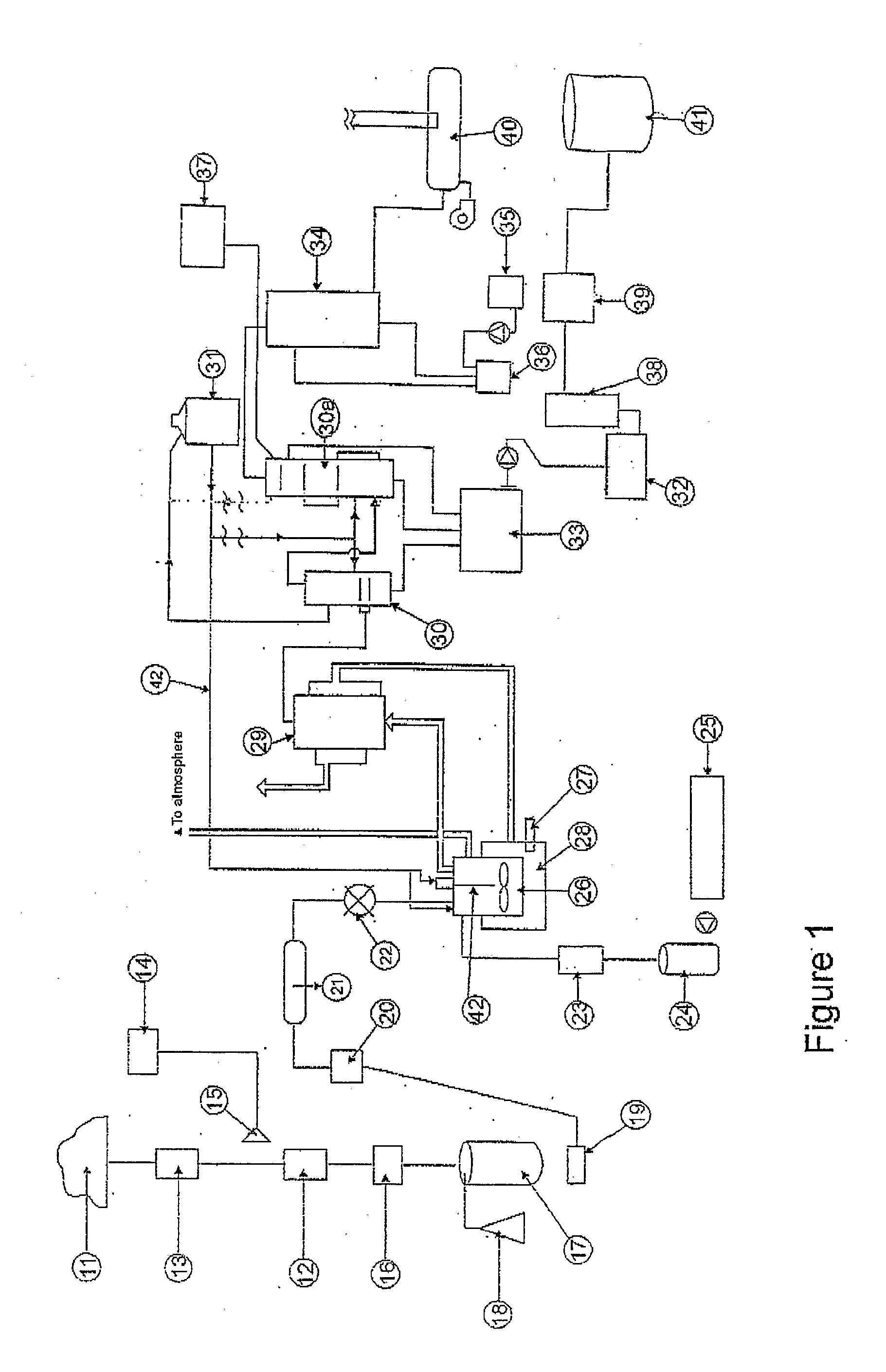
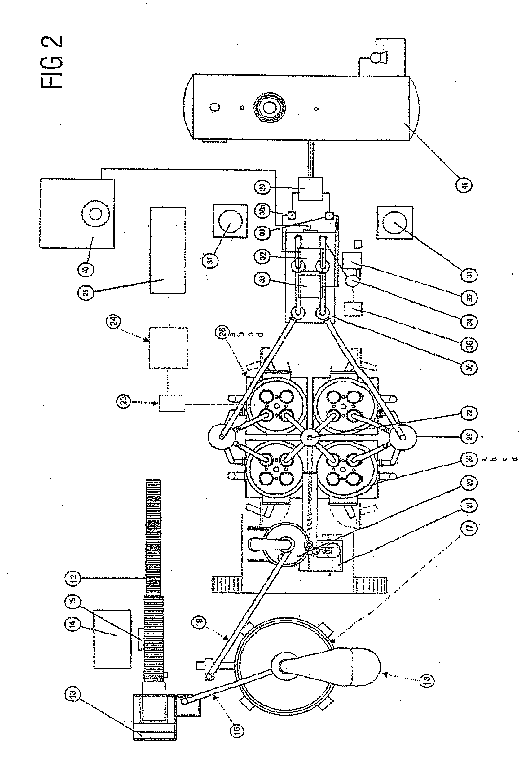
[0079] Referring to the figures wherein like reference numerals designate like or corresponding parts throughout the several views, and referring particularly to FIGS. 1, 2 and 3, an overview process 6 and plant set up for converting waste plastic to diesel fuel using a batch process according to the invention is shown.

Early Process Operation

[0080] Waste plastics in their original form of plastic sheets, drums, rolls, blocks and flat pieces are placed in a stockpile 11 and moved via an underfloor variable speed pan conveyor 13, through to a granulator 12 to reduce the size of the large items of waste plastic. An over-band magnet 15 and metals container (14) is situated above the conveyor 13 to remove any metals prior to entry into the granulator 12. From the granulator...


PUM


Abstract

A process and plant for the thermocatalytic conversion of waste materials into reusable fuels and a fuel produced by the process, involving the steps of delivering melted waste material (11) to one or more pyrolysis chambers (26) via heated and valved manifolds (22) and effecting pyrolysis of the waste material into a gascous state in an oxygen purged and pressure controlled environment. Pyrolytic gases are, then transferred to a catalytic converter (29) where the molecular structure of the gaseous material is altered in structure and form, with gases then transferred to one or more condensers (30a) to distil and cool gases in to their respective fractions. After post pyrolysis treatment, fuel fractions thon form a useable fuel. Includes the melting of waste (plastic) material (11) before delivery into any of the pyrolysis chambers (26), making the movement of material into the catalytic tower (29) a semi-continuous operation, directing melted waste material into one or more, but preferably four, pyrolysis chambers (26a, b, c, d), making each chamber capable of independent operation, optionally mechanically removing waste char from the pyrolysis chamber (107) by use of an internet auger (112) or other suitable means.

Description

FIELD OF INVENTION [0001] The present invention relates to the field of processing plastic and preferably waste plastic material into new products, which have valuable and useful properties. In one aspect, the present invention relates to a process for converting plastics to liquid hydrocarbons, particularly diesel fuel. It will be convenient to hereinafter describe the invention in relation to the conversion of plastics to diesel fuel, however it should be appreciated that the present invention is not limited to that use only. BACKGROUND ART [0002] Numerous unsuccessful attempts have been made in the past to efficiently reprocess a feedstock of waste plastics back into a liquid hydrocarbon product that has valuable and useful properties. A considerable tonnage of waste commodity plastics, or polymers, are improperly disposed of each year. In previous years, there there has been considerable improvement in the collection and recycling of common waste polymers. However, the recycling...

Claims


Application Information

Patent Timeline
IPC IPC(8): C10G1/10C10B57/04C10B47/18C10B53/07C10G1/00C10G11/02C10G11/05C10G11/10C10L1/08
CPCC10B47/18C10B53/07C10G1/02C10G1/10C10G2400/04C10G11/05C10G11/10C10L1/08C10G2300/1003C10G11/02Y02E50/30Y02P20/143C10L1/06C10B27/06C10L2200/0469C10L2270/026C10L2290/02C10L2290/06C10L2290/24C10L2290/28
Inventor BAKER, GARRY
Owner FUTURE ENERGY INVESTMENTS PTY LTD
Why Eureka
Try Eureka