Flashless welding method and apparatus

a welding method and flashless technology, applied in the field of welding, can solve the problems of splicing leaving an undesirable seam or flash, flash is particularly undesirable, and the extrusion can break, so as to improve the weld strength and appearance, eliminate flash, and eliminate the processing step and associated manufacturing costs

Active Publication Date: 2007-08-09
SPRINGSEAL
View PDF5 Cites 7 Cited by
  • Summary
  • Abstract
  • Description
  • Claims
  • Application Information

AI Technical Summary

Benefits of technology

[0012] In another exemplary embodiment, the first and second extrusion ends are no longer equally spaced about their respective molds. Instead, the spacer bar allows one of the ends to be offset, extending to a distance greater than the opposing extrusion relative to the face of the mold. The offset distance is controlled by the location of the spacer bar, which acts similar to a physical stop in a fixture. In this particular embodiment, the molds now perform the clamping function previously executed by a separate set of clamps. This is accomplished by keeping one of the clamping molds stationary, while the opposite clamping mold is a mobile mold capable of movement. Within the cavity of the mobile mold is the extrusion end having the greater offset, and at this point, the mold acts as a clamp and securely grips the offset extrusion end. The opposing stationary mold, although in contact with the second extrusion end forming a secure attachment, provides for movement of the second extrusion end.
[0013] The mobile mold is then advanced toward the stationary mold, plunging the offset end into the stationary mold making contact and adhering to the opposite extrusion end, while driving it back into the stationary mold. Just prior to the plunging operation the stationary mold was preheated and continues to be heated until the extrusion ends are in contact. After extrusion contact, the stationary mold is cooled, thereby improving both the weld strength and appearance while eliminating flash. The molds are then opened for the re...

Problems solved by technology

It is not uncommon for a break to occur in the extrudate for any number of reasons, including fatigue or stress on the extrusion, depletion of raw materials making up the compound, machine break-down, or operator neglect during the manufacturing process.
After the welding operation, the resulting splice can leave an undesirable seam or flash, which is not part of the finished product.
This flash is particularly undesirable in extruded profiles that perform a sealing function.
In addition, the flash generates extra cost to the product by requiring an additional deflashing operation, either manually by an operator or a ...

Method used


Image

  • Flashless welding method and apparatus
  • Flashless welding method and apparatus
  • Flashless welding method and apparatus

Examples


Embodiment Construction

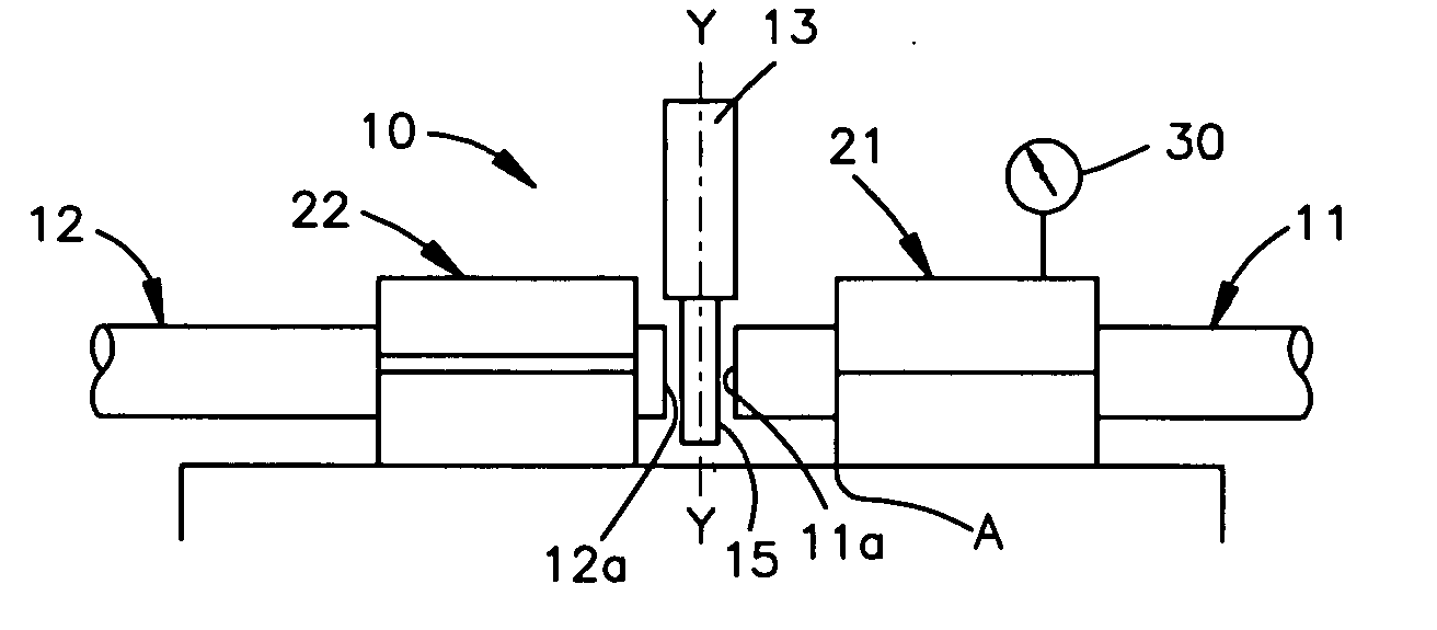
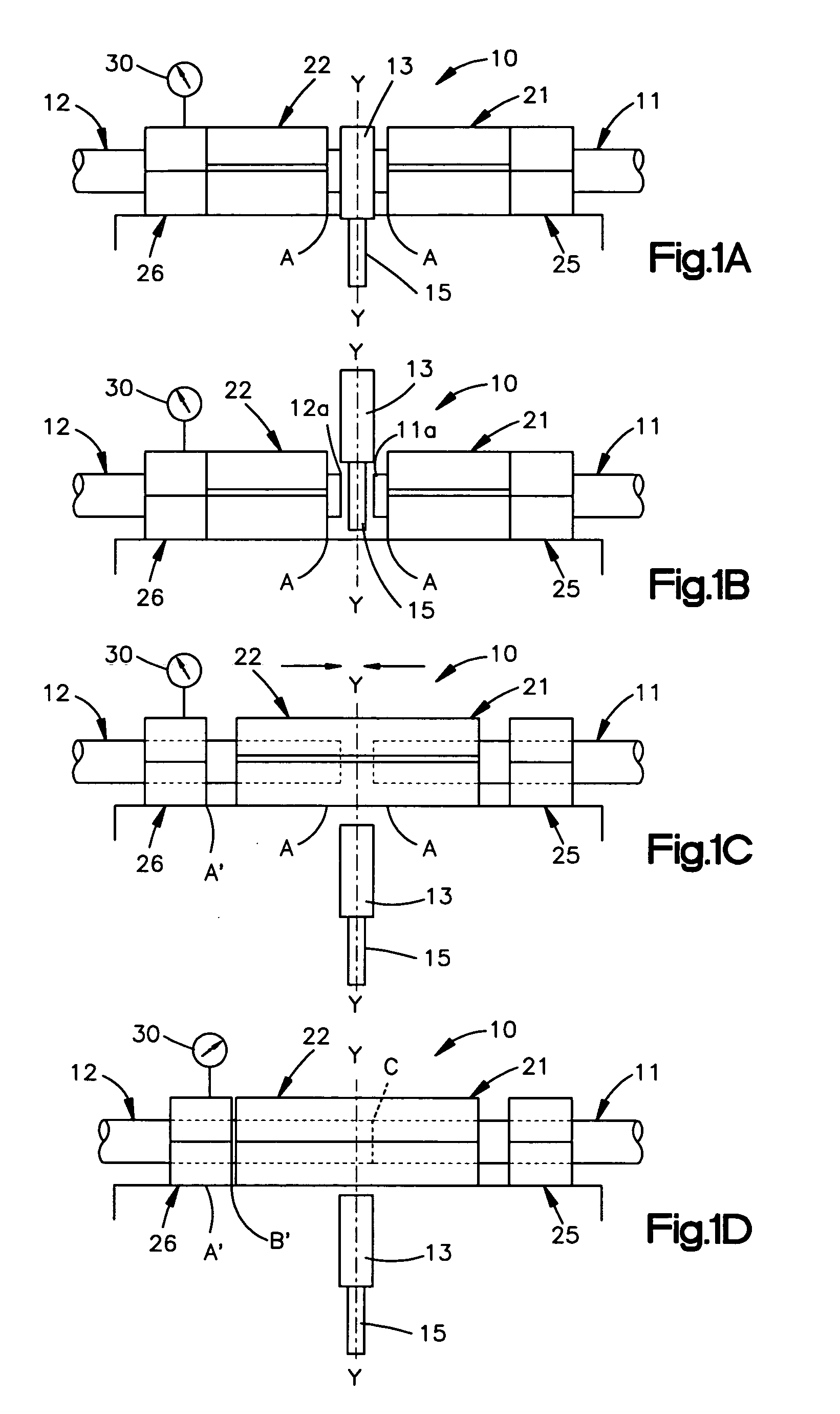
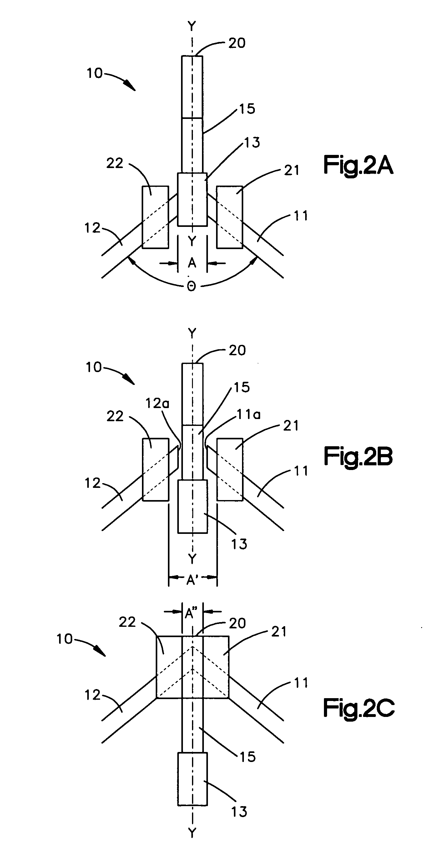
[0040]FIG. 1A is a schematic depiction of an extrusion welding system 10 having a first and a second extrusion end, 11 and 12, respectively placed in a loading position. The extrusions represent the ends of two articles or the opposite ends of a single article. The extrusion may include a gasket having thermal plastic properties requiring a connection to form an endless flashless product. Alternatively, the extrusions may connect two separate extrusions together to form a finished product having separate opposite ends, or include forming an extrudate that requires a connection between two separate extrusions to form a continuous roll stock.

[0041] The welding system is capable of seamlessly welding extrusion compositions typically classified as thermal plastic material, such as and including without limitation, Acrylonitrile-Butadiene-Styrene (“ABS”), Polyvinyl Chloride Plastic (“PVC”), Polystyrene, Polyolefinic materials such as polypropylene, and polyethylene, Thermoplastic Elasto...


PUM

PropertyMeasurementUnit
Fractionaaaaaaaaaa
Fractionaaaaaaaaaa
Angleaaaaaaaaaa

Abstract

A method and apparatus for welding two separate ends of an extrusion or two separate extrusion ends to form a flashless extrudate or gasket by having a first and a second mold for supporting and clamping the extrusion ends, and a spacer bar for positioning the extrusion ends to a location within the mold. A heating element elevates the temperature of the extrusion ends to a welding condition, and a clamping device is used for securing the extrusion ends. A flashless welding operation results by inserting and clamping at least one heated extrusion end into a welding mold until an acceptable contact pressure is obtained against the opposing heated extrusion end.

Description

FIELD OF THE INVENTION [0001] The present invention concerns both methods and apparatus relating to the welding of various materials together generally, and more specifically, it relates to the improvements in the welding process that results in a flashless connection between separate articles or opposite ends of a single article. Background Art [0002] Several different methods of extruding thermal plastics are well known in the industry, including methods for both cold and hot feed extrusion. There is an infinite number of extrusion profiles that can be extruded depending on the shape and contour of the particular die used in the extrusion process. The four most common extrusion profiles are tubing, channel, cord and bulb seals. [0003] Finished extruded material can be made into continuous rolls of varying length, generally referred to in the industry as extrudate. The length of the extrudate roll is typically specified from a customer's stock order. Alternatively, the finished ext...

Claims


Application Information

Patent Timeline
IPC IPC(8): B23K31/02
CPCB29K2055/02B29C66/92651B29L2031/265B29L2031/709F16J15/108B29L2031/003B29C66/92211B29C66/91931B29C66/91921B29C47/0014B29C47/0023B29C47/0026B29C47/0066B29C47/56B29C65/1432B29C65/7802B29C66/1142B29C66/1162B29C66/324B29C66/5241B29C66/5243B29C66/80B29C66/919B29C66/9241B29K2021/003B29K2023/00B29K2023/06B29K2023/12B29K2025/00B29K2027/06B29C65/103B29C65/1467B29C65/1632B29C66/5221B29C66/52431B29C66/91411B29C66/91421B29C66/91445B29C66/9221B29C65/00B29C65/20B29C66/71B29C66/73921B29C48/0022B29C48/05B29C48/09B29C48/10B29C48/49B29K2025/06
Inventor KNAPP, MARK
Owner SPRINGSEAL
Why Eureka
Try Eureka