Supercharge Your Innovation With Domain-Expert AI Agents!

Voltage level shifter circuit

a technology of voltage level and shifter, which is applied in the direction of logic circuits, power consumption reduction, information storage, etc., can solve the problems of increasing the area required, reducing the crowbar current consumption, and not being able to solve low-power processes, etc., and achieves a small area, minimizing crowbar current, and minimizing loading.

Inactive Publication Date: 2007-08-09
CONVERSANT INTPROP MANAGEMENT INC
View PDF13 Cites 2 Cited by
  • Summary
  • Abstract
  • Description
  • Claims
  • Application Information

AI Technical Summary

Benefits of technology

[0013] It is an object of the present invention to provide a level shifter circuit having minimal loading on a preceding logic circuit while occupying a small area and minimizing crowbar currents.

Problems solved by technology

However, since current leakage is a growing problem in small geometry semiconductor processes, this solution may not be available for low power processes where only high Vt devices can be fabricated.
Smaller device sizes in level shift circuitry also result in lower crowbar current consumption.
Additionally, a larger load on that same logic circuit can require the use of larger device sizes in both the logic circuit and level shifter, increasing the area required.
The additional cost of a multiple Vt fabrication process which might enable smaller device sizes may not be acceptable either.

Method used


Image

  • Voltage level shifter circuit
  • Voltage level shifter circuit
  • Voltage level shifter circuit

Examples


Embodiment Construction

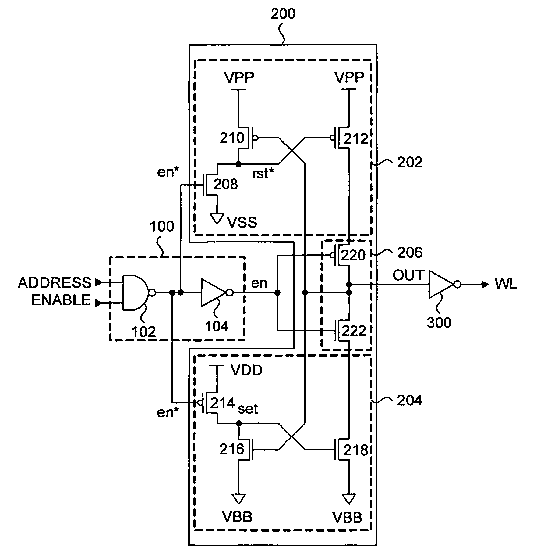
[0025] A level shifter circuit for converting a logic signal with high and low logic voltage levels at the logic supply voltages to a signal with a high voltage level above the high logic voltage level and a low voltage below the low logic voltage level is disclosed. The disclosed level shifter circuit reduces the load on the logic circuit used for switching the state of the level shifter, minimizes crowbar currents and occupies a small area thus facilitating its layout in pitch-limited areas, without a significant change in performance.

[0026]FIG. 3 is a circuit schematic of a level shifter circuit according to an embodiment of the present invention. FIG. 3 includes a logic circuit 100, a level shifter circuit 200, and a buffer 300. The level shifter circuit 200 will convert or translate a logic signal having first high and low supply voltage levels to a signal having second high and low supply voltage levels. The second high supply voltage level is greater than the first high supp...


PUM


Abstract

A level shifter circuit for converting a logic signal with logic ‘1’ and ‘0’ levels at first high and low supply voltage levels to a signal with second high and low supply voltage levels. In particular, the second high and low supply voltage levels are greater than the first high and low supply voltage levels. The disclosed level shifter is configured such that the size of the preceding logic gate and circuitry within the level shifter can be reduced, facilitating its layout in pitch-limited areas. The level shifter also includes circuitry to decouple the output pull-up and pull-down paths to further facilitate state transitions and reduce crowbar current consumption.

Description

TECHNICAL FIELD [0001] The present invention generally relates to level shifter circuits. In particular, the present invention relates to two voltage level shifter circuits. BACKGROUND INFORMATION [0002] Voltage level shifting circuits are well known in the art for translating, or converting, digital signals driven with a first set of voltage supplies to a signal driven with a second set of voltage supplies, where the high (or low) voltage output is higher (or lower) than that in the first set of voltage supplies. Voltage level shifting is used in systems where circuits operating with different voltage supplies must communicate with each other. [0003] Those of skill in the art will understand that dynamic random access memory (DRAM) conventionally employs level shifters in the wordline driver circuits of a memory array. The wordline driver circuits in a memory with n-channel cell transistors preferably drive wordlines with a voltage above the logic ‘1’ power supply voltage (typicall...

Claims


Application Information

Patent Timeline
Patent Type & Authority Applications(United States)
IPC IPC(8): H03K19/0175
CPCG11C8/08H03K19/018521H03K19/0013G11C11/4085H03K5/003H03K5/02H03K19/0175
Inventor LINES, VALERIE L.
Owner CONVERSANT INTPROP MANAGEMENT INC
Features
  • R&D
  • Intellectual Property
  • Life Sciences
  • Materials
  • Tech Scout
  • Unparalleled Data Quality
  • Higher Quality Content
  • 60% Fewer Hallucinations
Learn More