Radio frequency technology heater for unconventional resources

Active Publication Date: 2007-08-16
PYROPHASE
View PDF84 Cites 96 Cited by
  • Summary
  • Abstract
  • Description
  • Claims
  • Application Information

AI Technical Summary

Benefits of technology

[0024] A goal of this invention is to develop a very robust RFT (Radio-Frequency-Technology) thermal diffusion tubular or rod-like heater system to extract fuel from unconventional deposits, such as oil shale, using for the most part conventional oil field components, such as 0.5% carbon steel tubing or casing. Another goal is to be able during field installation to change the material or geometry of the conductors to tailor the heating pattern in accordance with the reservoir properties of the deposit or product recovery methods. Another goal is to tailor the geometry and materials of the tubular conductors to resist down-hole pressures and stresses without impairing the heating functions. Another goal is to use conventional oil field components and installation method. Other goals are to be able to use the system either as heat-only to stimulate production, or as a combination heater/product-collector version; limit the

Problems solved by technology

Conventional extraction processes are often costly; in the case of oil shale or oil sands, the resources are first mined and then heated in an above ground process to extract the oil.
Such approaches, if applied in large scale, are environmentally difficult and can generate large amounts or CO2 and spent shale or oil sand leavings.
Conventional mining and heating methods use thermal diffusion of heat from the outside to the inside of a block of oil shale; this takes a long time, unless the size of the volume being heating is very small.
So far, the challenge has been finding an efficient heater that can k

Method used


Image

  • Radio frequency technology heater for unconventional resources
  • Radio frequency technology heater for unconventional resources
  • Radio frequency technology heater for unconventional resources

Examples


Example

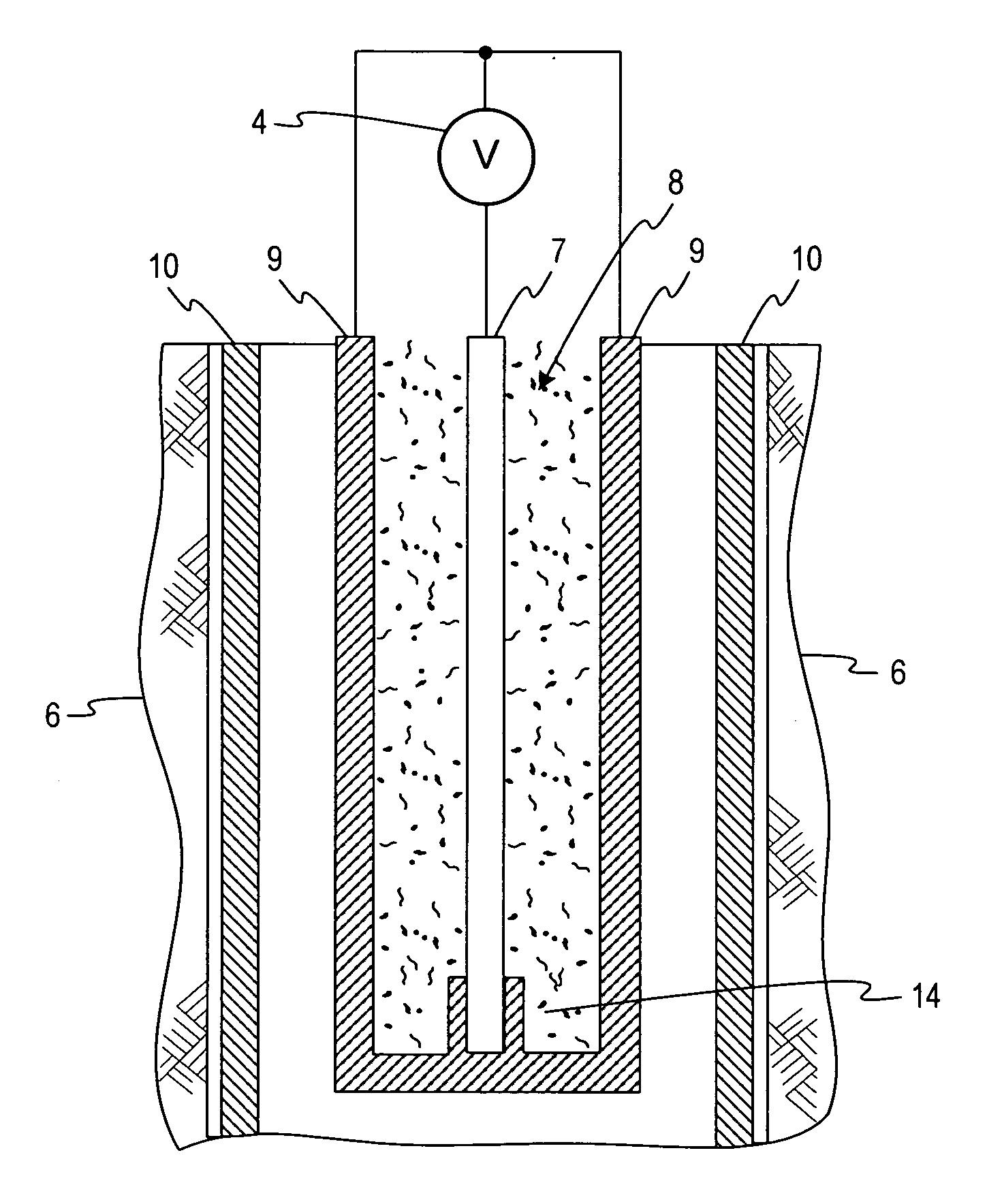
[0043] This invention utilizes frequency-variable electromagnetic RFT heating techniques to heat commonly available (although not limited to) magnetic low carbon steel tubing or rods, such as used in oil fields. RFT heating techniques include technology used to design radio-frequency communication systems that employ frequencies as low as 7 Hz (such as the Schuman Resonance proposed for submarine command and control) and up to 5 MHz (for short wave communications).

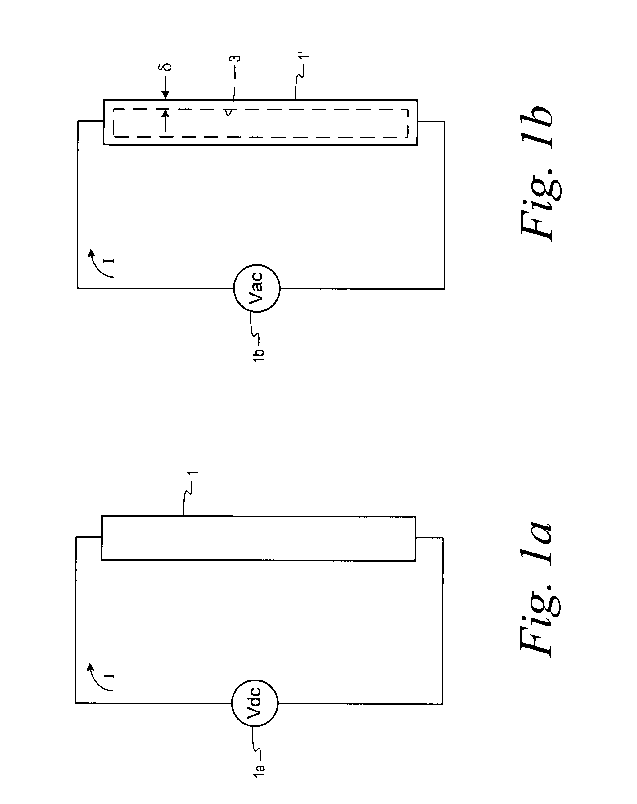
[0044] To illustrate, FIG. 1A represents a 1 meter long thin (e.g., about 3 mm) diameter rod 1 of magnetic steel. This rod is connected to a d-c voltage source 1a. The current, I through the rod is simply determined by dividing the d-c source V by the resistance of the rod (e.g., about 1.6×10⁻² ohms). If connected to 1-volt source, over 60 watts would be dissipated. To lower the dissipation to 10 watts, the diameter of the rod would have to be substantially reduced by a factor of 2 or 3 (this is why the filaments in light...


PUM


Abstract

A system for heating at least a part of a subsurface hydro carbonaceous earth formation forms a borehole into or adjacent to the formation, places elongated coaxial inner and outer conductors into the borehole with the inner and outer conductors electrically connected to each other at a depth below the top of the formation, and connects an AC power source to at least the outer conductor to produce heat in at least one of the conductors. The AC output has a controlled frequency, and the outer conductor comprises a standard oil well component made of a ferromagnetic material that conducts current from the AC power source in only a surface region of the conductor due to the skin effect phenomenon. More heat is dissipated from portions of the conductor that is within the depth range of the formation than from other portions of the conductor. The inner conductor may optionally be a standard tubular oil well component made of a ferromagnetic material that conducts current from the AC power source in only a surface region of the conductor due to the skin effect phenomenon.

Description

CROSS-REFERENCE TO RELATED APPLICATIONS [0001] This application claims priority to U.S. Provisional Application Ser. No. 60 / 759,727 filed Jan. 19, 2006.FIELD OF THE INVENTION Background [0002] Unconventional resources such as oil shale, oil sands and tar sands contain several trillions of barrels in deposits in North America. These deposits require heating to extract the oil. Conventional extraction processes are often costly; in the case of oil shale or oil sands, the resources are first mined and then heated in an above ground process to extract the oil. Such approaches, if applied in large scale, are environmentally difficult and can generate large amounts or CO2 and spent shale or oil sand leavings. Conventional mining and heating methods use thermal diffusion of heat from the outside to the inside of a block of oil shale; this takes a long time, unless the size of the volume being heating is very small. [0003] To mitigate the cost and environmental issues, in situ heating metho...

Claims


Application Information

Patent Timeline
IPC IPC(8): E21B43/24
CPCE21B36/04E21B43/2401E21B43/24E21B43/2408
Inventor BRIDGES, JACK E.
Owner PYROPHASE
Why Eureka
Try Eureka