
Plasma ion mobility spectrometer

Inactive Publication Date: 2007-08-16
BROMBERG LESLIE +2
View PDF46 Cites 16 Cited by
  • Summary
  • Abstract
  • Description
  • Claims
  • Application Information

AI Technical Summary

Benefits of technology

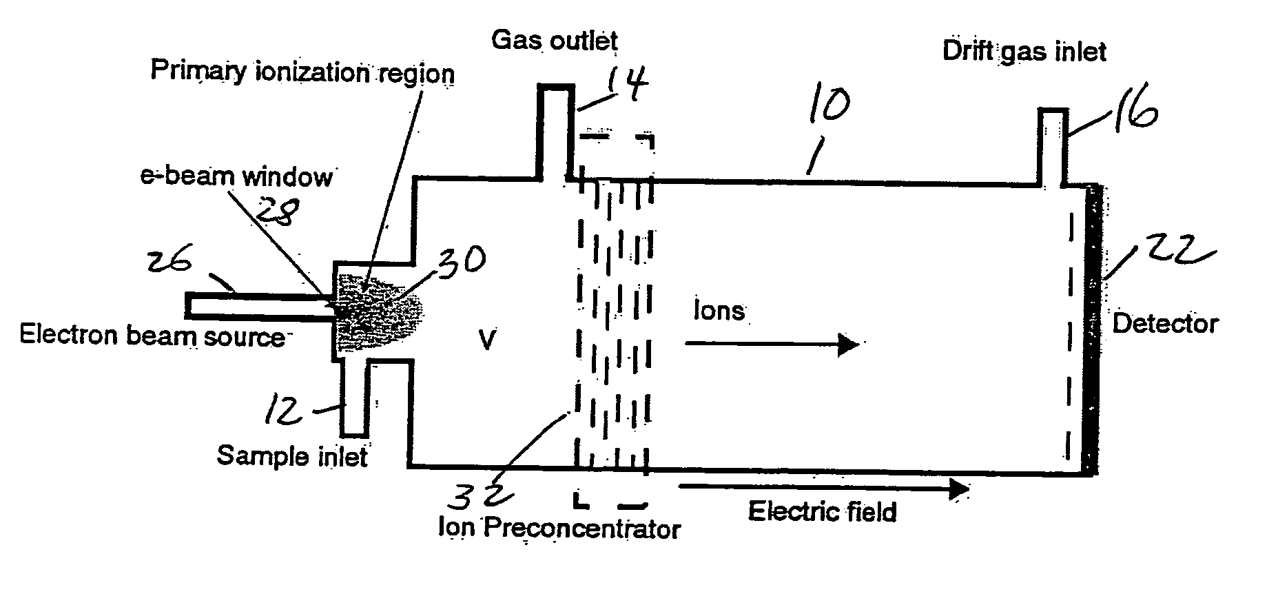
[0018] In one aspect, the invention is an ion mobility spectrometer having an enclosure for receiving a sample therewithin. The spectrometer includes an electron beam window for admitting an electron beam into the enclosure to ionize the sample in an ionization region. A shutter grid is spaced apart from the ionization region and means are provided for sample ion preconcentration upstream of the shutter grid. It is preferred that the ion preconcentration be effective to reduce space charge resulting in a lowered threshold detection level.
[0021] The varying electric field may be an asymmetric field such as an asymmetric square wave (a periodic signal whose voltage is varied from positive to negative, with unequal positive and negative voltages, and / or different times during which the positive or the negative ions are applied). It is preferred that the asymmetric field be selected to optimize ion preconcentration. It is also preferred that timing of opening of the shutter grid is synchronized with the varying electric field. It is also preferred that the shutter grid be opened when sample ions are closest to the shutter grid. It is preferred that the grid include grid wires having a characteristic size and spacing less than the spacing between grids. It is preferred that the grids be a 2-dimensional pattern, fabricated using microfabrication or microlithographic techniques. Smaller feature sizes result in reduced distortion of the electric fields in the region upstream from the shutter and the preconcentrator, and improved introduction of the ion cloud to the shutter or to the preconcentrator.

Problems solved by technology

Moreover, there are cases (where the ions quickly form cluster ions, for example) where the ion loss is not determined by ion recombination.
However, conventional technologies present issues with the size of DC power supplies (including the transformer), the size of the high voltage insulators and other issues dealing with high voltage such as arcing.
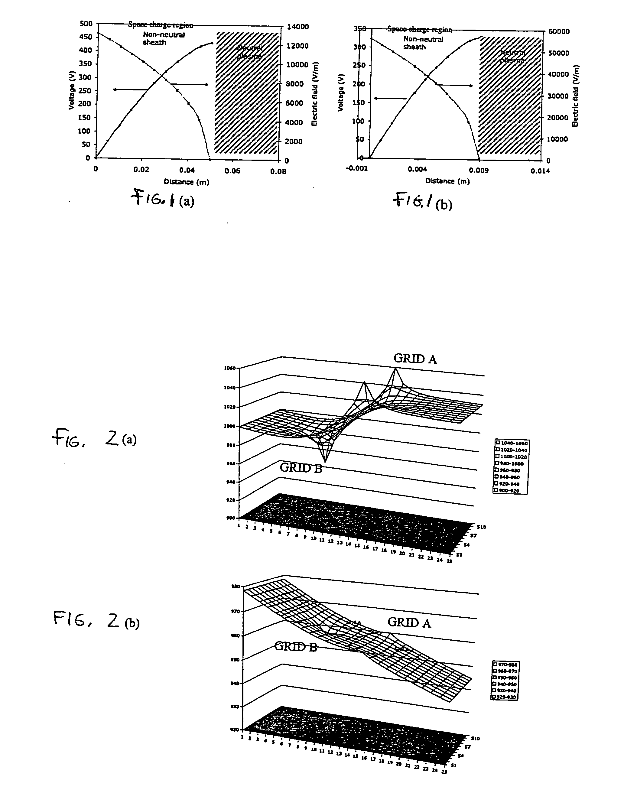
High space charge at the higher ion concentration limits the resolution by spreading the peaks and by ion radial loss in the drift column due to space charge.
However, the separation in this approach (FAIMS / MS) occurs in the drift region, and does not solve the problem of high space charge.
Conventional injection methods would result in space charge dominated flow in the drift region, with loss of resolution and corresponding increase in Minimum Detection Level.
In the drift region, the space charge limits the resolution of the instrument.
With 2 nA current in the drift region, present day IMS have substantial space charge to result in substantial spreading of the ion cloud (and therefore loss of resolution and selectivity).
It has been known that the resolution (selectivity) limitation due to diffusion depends on the voltage applied across the drift region.
Although a large amount of literature exists on IMS devices, little is said about ion handling upstream from the shutter.

Method used


Image

  • Plasma ion mobility spectrometer
  • Plasma ion mobility spectrometer
  • Plasma ion mobility spectrometer

Examples


Embodiment Construction

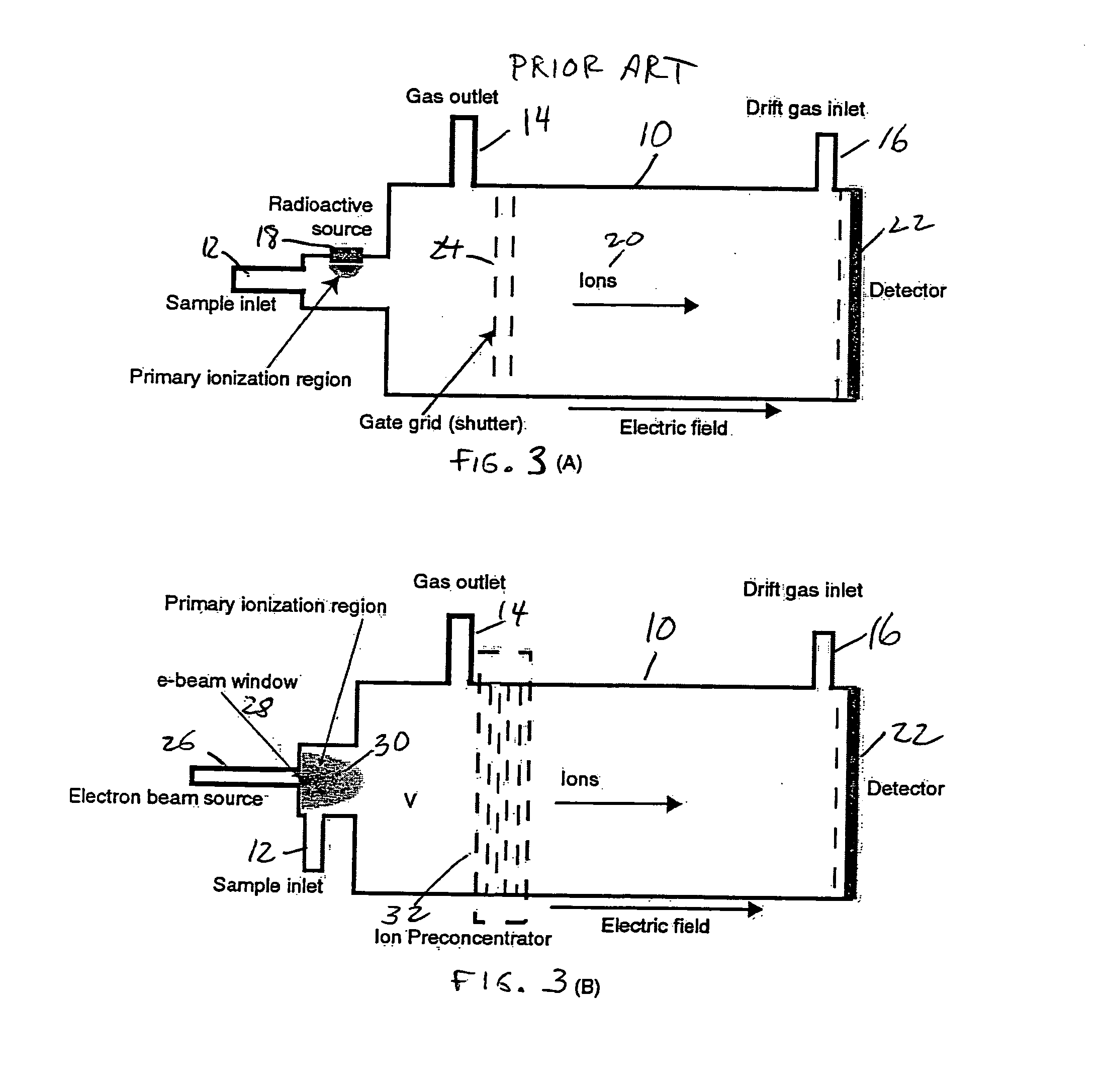
[0038] High energy electron beams have been proposed for use with an IMS (VIP Sources for Ion Mobility Spectrometry H.-R. During, G. Arnoldl, V. L. Budovich, Bruker Saxonia Analytik GmbH, Leipzig, Germany and CHROMDET ANALYTICAL INSTRUMENTS, Moscow, Russia). The advantages of using electron beams are pulsed operation, high instantaneous and average currents (related to dose rates) and capability for varying the current. The use of high current dose rate results in high reactive ion density. A high reactive ion density is good in that it is possible to decrease the Minimum Detection Limit (MDL), by ionizing a larger fraction of the molecules of interest. However, to our knowledge, the advantage of using e-beam ionization has not ever been realized. The apparent failure to realize this advantage may be due to space charge effects in the drift region. Conventional IMS devices, as well as an e-beam enhanced one, are shown in FIGS. 3a and 3b.

[0039] A conventional, prior art ion mobility...


PUM


Abstract

Ion mobility spectrometer. The spectrometer includes an enclosure for receiving a sample therewithin and an electron beam window admits an electron beam into the enclosure to ionize the sample in an ionization region. A shutter grid is spaced apart from the ionization region and means are provided for sample ion preconcentration upstream of the shutter grid. The ion preconcentration is effective to reduce space charge resulting in a lowered threshold detection level.

Description

[0001] This application claims priority to Provisional Patent Application Ser. No. 60 / 550,640 filed Mar. 5, 2004, the contents of which are incorporated herein by reference. This application is a continuation of and also claims priority to Utility patent application Ser. No. 10 / 865,548 which is also U.S. Pat. No. 7,105,808.BACKGROUND OF THE INVENTION [0002] Ion Mobility spectrometers (IMS) have been developed for very sensitive monitoring of chemical species. An important application of the technology is its use to detect trace quantities of explosive material and chemical agents in compact devices. Trace ions of a subject material are separated by using the fact that the electrical mobility of different ion species is different. Time of flight measurements are made. Once chemical species are separated, the ionic current is measured using an electrometer. [0003] Presently, most IMS devices use for ionizing a sample either a radioactive source (Ni63 being the most common, although T3...

Claims


Application Information

Patent Timeline
IPC IPC(8): B01D59/44
CPCH01J49/40H01J49/004
Inventor BROMBERG, LESLIEHADIDI, KAMALCOHN, DANIEL R.
Owner BROMBERG LESLIE
Learn More