Check patentability & draft patents in minutes with Patsnap Eureka AI!

Light emitting device

a technology light source, which is applied in the field can solve the problems of low brightness, large size of light emitting device, and increase power consumption, and achieve the effects of reducing size, high brightness, and reducing power consumption

Active Publication Date: 2007-08-16
NICHIA CORP
View PDF19 Cites 76 Cited by
  • Summary
  • Abstract
  • Description
  • Claims
  • Application Information

AI Technical Summary

Benefits of technology

[0009]It is an object of the present invention to provide a novel light emitting device that has high brightness and is suited to reducing the size, has reduced power consumption, and emits green light using a laser diode as a light source.
[0010]It is another object of the present invention to provide a novel light emitting device can be provided with which it is possible to increase the luminous flux that is emitted.
[0030]With the present invention, since light of a specific wavelength can be taken out from a light emitting device, it is possible to provide a novel light emitting device that has high brightness and is suited to reducing the size, has reduced power consumption, and emits green light using a laser diode as a light source. Also, with the present invention, a novel light emitting device can be provided with which it is possible to increase the flux of light that is emitted.

Problems solved by technology

With this light emitting device, the light source may in some cases be an LED, but a problem with an LED is its low brightness.
Also, the light source may in some cases be an SHG laser or other such solid-state laser or a gas laser, but because these entail a complicated structure, the light emitting device becomes large and power consumption goes up.
Also, it will be necessary in the future to further increase the luminous flux emitted from a light emitting device, but at the present time the luminous flux of emitted light is not large enough to meet future needs.

Method used


Image

  • Light emitting device
  • Light emitting device
  • Light emitting device

Examples


embodiment 1

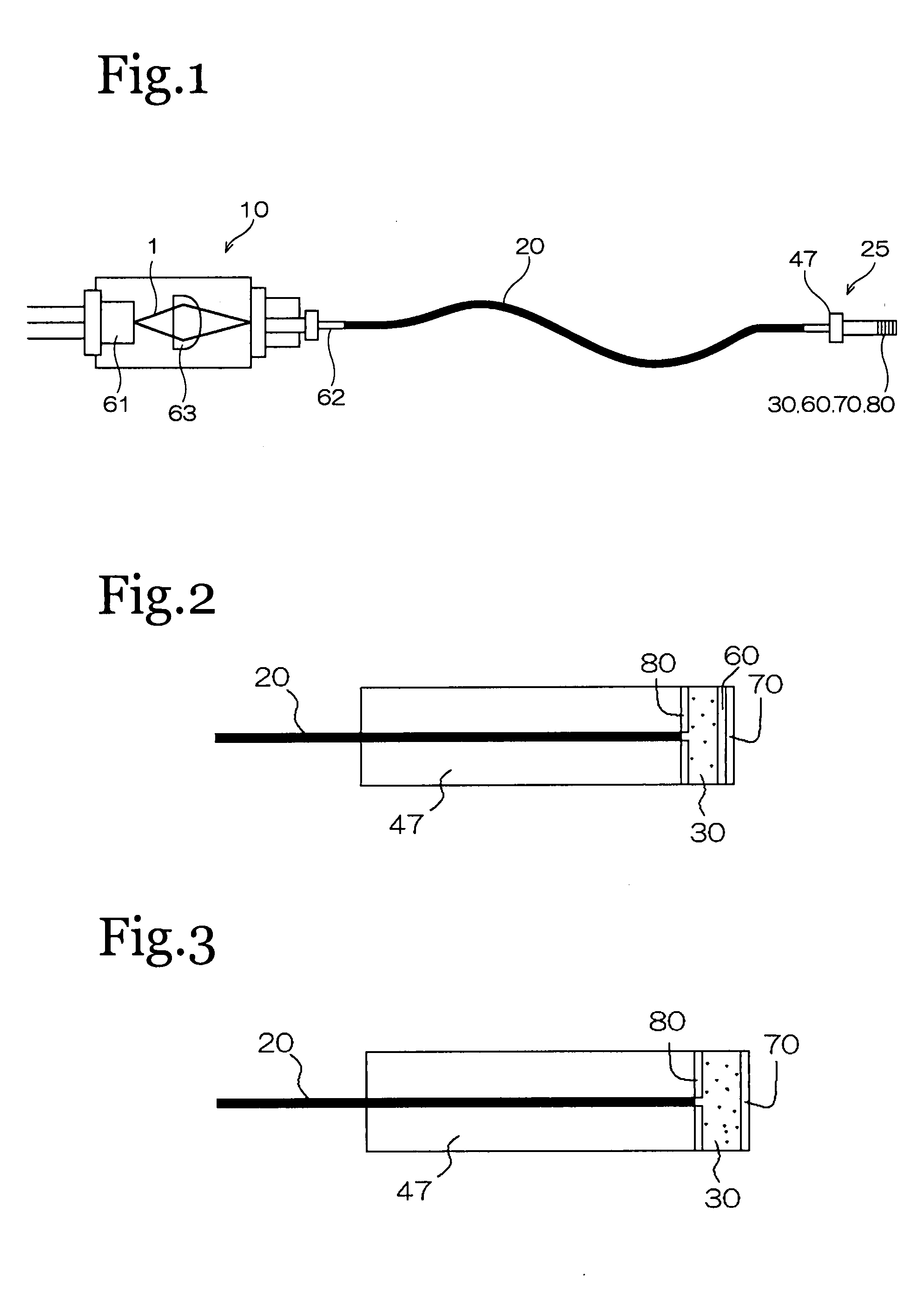
[0045]As shown in FIG. 1, the light emitting device of the present invention mainly comprises a light source 10, a light guide 20, a light guide end member 47, a wavelength conversion member 30, a reflection member 60, and a shielding member 70.

[0046]As shown in FIG. 2, the light guide end member 47 is provided on the emission side of the light guide 20, and a reflective film 80 that reflects light of a predetermined (specific) wavelength is formed at the end face of this light guide end member 47. The wavelength conversion member 30 is attached to the light guide end member 47 with the reflective film 80 sandwiched in between, the reflection member 60 is attached to the emission side of the wavelength conversion member 30, and the shielding member 70 is attached to the emission side of the reflection member 60.

Light Source 10

[0047]The light source 10 emits excitation light, and may emit any light as long as it allows a fluorescent substance (discussed below) to be excited. As shown...

embodiment 2

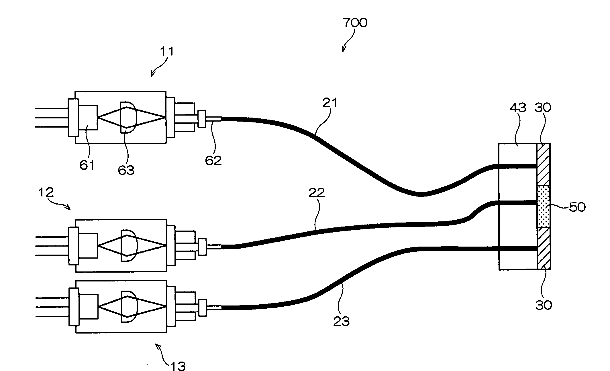
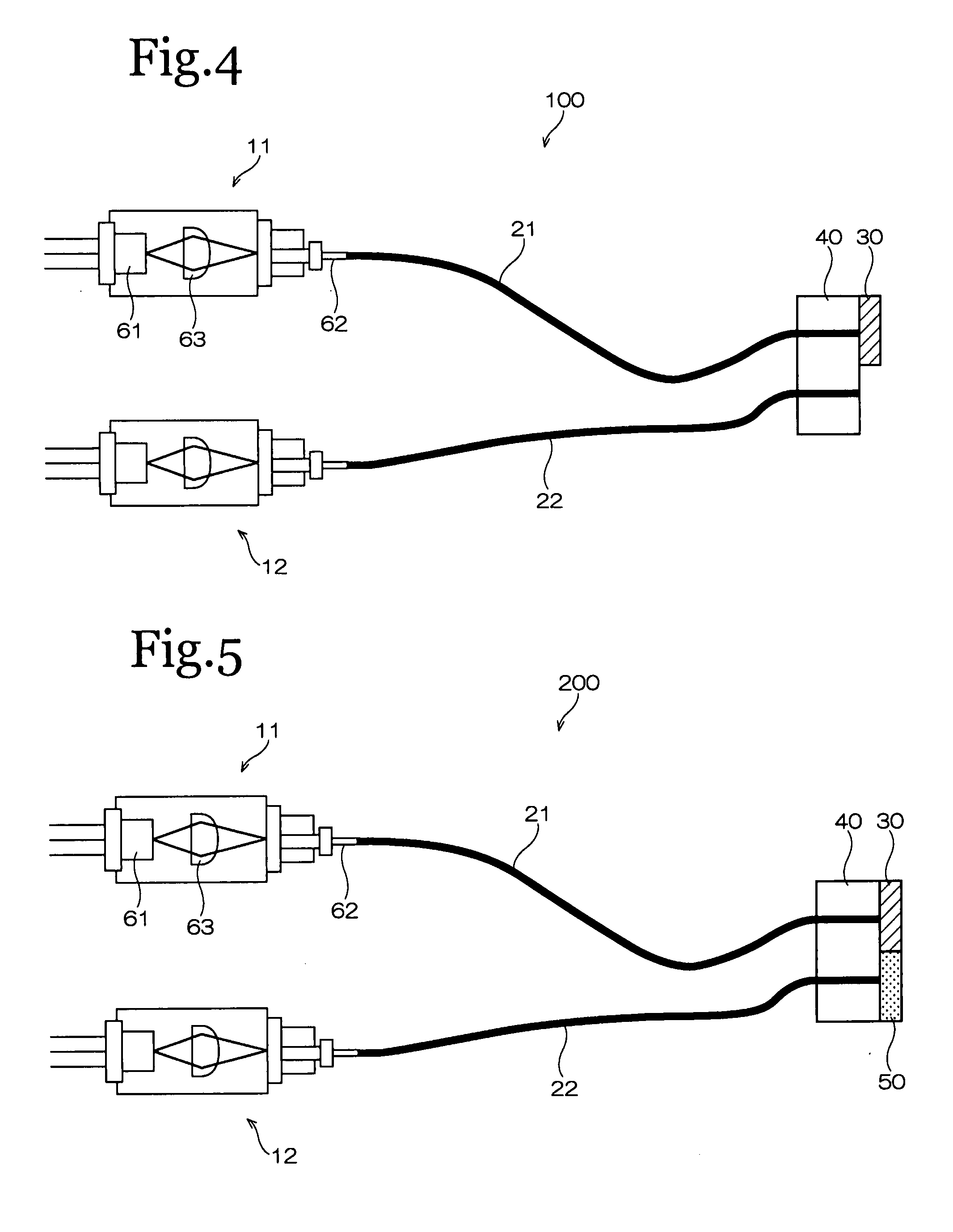
[0087]As shown in FIG. 4, the light emitting device 100 of the embodiment comprises a first light source 11, with an emission peak wavelength in a wavelength band of 400 to 500 nm, a second light source 12, with an emission peak wavelength in a wavelength band of 600 to 700 nm, a first light guide 21 having at least one optical fiber for propagating the light emitted by the first light source 11, in which the refractive index of the center part (core) of a cross section is higher than the refractive index of the peripheral part (cladding), a second light guide 22 having at least one optical fiber for propagating the light emitted by the second light source 12, a wavelength conversion member 30 that is provided to just the end on the emission side of the first light guide 21, absorbs the light propagated by the first light guide 21 and converts the wavelength thereof, and releases light having an emission peak wavelength in a wavelength band of 450 to 650 nm.

[0088]With the light emit...

embodiment 3

[0091]As shown in FIG. 5, this light emitting device 200 differs from the light emitting device 100 pertaining to the first embodiment in that a diffusion material 50 is provided to the end on the emission side of the second light guide 22. Doing this reduces unevenness in the color of the light emitted from the light emitting device 200.

[0092]The diffusion material 50 is a resin, for example, and preferably one with a relatively high refractive index, the product of adding the above-mentioned filler to the above-mentioned resin, or the like. It is especially favorable to use a silicone resin that contains a filler.


PUM


Abstract

A light emitting device, comprises: a light source that emits excitation light; a light guide that propagates the excitation light, and in which the refractive index of the center part (core) of a cross section is higher than the refractive index of the peripheral part (cladding); a wavelength conversion member that absorbs the excitation light propagated by the light guide and converts the wavelength thereof, and releases light of a predetermined wavelength band; and a shielding member that blocks the wavelength of at least part of the excitation light and the light emitted from the wavelength conversion member.

Description

BACKGROUND OF THE INVENTION[0001]1. Field of the Invention[0002]The present invention relates to a light emitting device, and more particularly to a light emitting device that can be utilized in laser displays, projector devices, endoscopes, and so forth.[0003]2. Background Information[0004]With laser displays, projector devices, endoscopes, and so forth, light of various wavelengths is combined to produce light of the desired wavelength (see Japanese Laid-Open Patent Application 2005-205195, for example), and this requires a light emitting device that is capable of emitting the blue, red, green, or other light that is to be combined.[0005]For example, there is a projector device comprising a semiconductor laser (as a solid-state light source that emits blue light with a wavelength of 405 nm), an optical fiber having a core doped with a wavelength downward conversion material for converting excitation light to blue, an optical fiber having a core doped with a wavelength downward con...

Claims


Application Information

Patent Timeline
IPC IPC(8): H01S3/091
CPCA61B1/0653C09K11/7734C09K11/7789C09K11/7741C09K11/7774C09K11/7738C09K11/77348
Inventor NAGAHAMA, SHINICHIHAMA, ATSUTOMOSUGIYAMA, TAKAFUMIKISHIMOTO, TOMOHISA
Owner NICHIA CORP
Features
  • R&D
  • Intellectual Property
  • Life Sciences
  • Materials
  • Tech Scout
  • Unparalleled Data Quality
  • Higher Quality Content
  • 60% Fewer Hallucinations
Learn More