
Substrate processing apparatus

a processing apparatus and substrate technology, applied in semiconductor/solid-state device testing/measurement, bridge structural details, construction, etc., can solve the problems of mechanical damage the thickness of the soi layer is reduced, and the present polishing is difficult to stop, so as to achieve the effect of facilitating the thickness control of the soi layer, eliminating major factors, and high surface planarity

Inactive Publication Date: 2007-08-16
CANON KK
View PDF15 Cites 221 Cited by
  • Summary
  • Abstract
  • Description
  • Claims
  • Application Information

AI Technical Summary

Benefits of technology

The present invention provides a method for manufacturing a substrate with a silicon layer on an insulating layer that can control the thickness of the silicon layer and reduce defects. This is achieved by performing a thinning step with a unit thinning step including an oxidation step and a removal step. Additionally, the invention provides a substrate processing apparatus that can chemically etch a semiconductor layer and measure the thickness of the layer in real-time to stop the etching process when the desired thickness is reached. The invention also provides a method for manufacturing a semiconductor substrate by forming a semiconductor substrate, chemically etching the semiconductor layer, measuring the film thickness, and stopping the etching process when the desired film thickness is reached.

Problems solved by technology

Since polishing is a machine work, it is difficult for the present to stop polishing so as to maintain a high precision of ±1 nm or less with respect to a target film thickness.
A stress which may be generated by these steps is more likely to cause defects with a decrease in thickness of the layer to serve as the SOI layer.
However, in polishing, the SOI layer is mechanically damaged to cause defects.
In both of sacrificial oxidation and etching using the SC-1 cleaning solution, the surface roughness of the SOI layer may degrade.
If process conditions vary due to a change in concentration of a chemical solution or the like, it is difficult to precisely control the etching amount or film thickness.
This makes the work inefficient.

Method used


Image

  • Substrate processing apparatus
  • Substrate processing apparatus
  • Substrate processing apparatus

Examples


first example

[0138] This example provides a result obtained by comparing a thinning step in units of a predetermined thickness not more than that of one lattice according to the present invention with another method. FIG. 12 is a table comparing the rms values (1 μm□, 2 μm□, 5 μm□, 10 μm□, and 20 μm□) of the surfaces of SOI substrates obtained after thinning, i.e., when a thinning step is performed according to the present invention (“present invention” in FIG. 12), when oxide film etching is performed after thermal oxidation (“after thermal oxidation / oxide film etching” in FIG. 12), and when etching using SC-1 is performed (“after SC-1 etching” in FIG. 12).

[0139] With the thinning step in units of the predetermined thickness not more than that of one lattice according to the present invention, the microroughness of a thin film degrades extremely slightly.

example 2

[0140] This example provides the film thickness distribution of an SOI layer before and after a thinning step in units of a predetermined thickness not more than that of one lattice according to the present invention.

[0141]FIG. 13 shows results obtained by measuring the film thickness distribution of the SOI layer at 17 in-plane points (Position=1 to 17) of an SOI substrate before and after thinning the SOI substrate by 40 nm using the predetermined thickness not more than that of one lattice according to the present invention. With the thinning step according to the present invention, the variation range of the in-plane film thickness of the SOI substrate is kept extremely small even after the thinning.

example 3

[0142] This example provides an application of the present invention to ELTRAN (registered trademark).

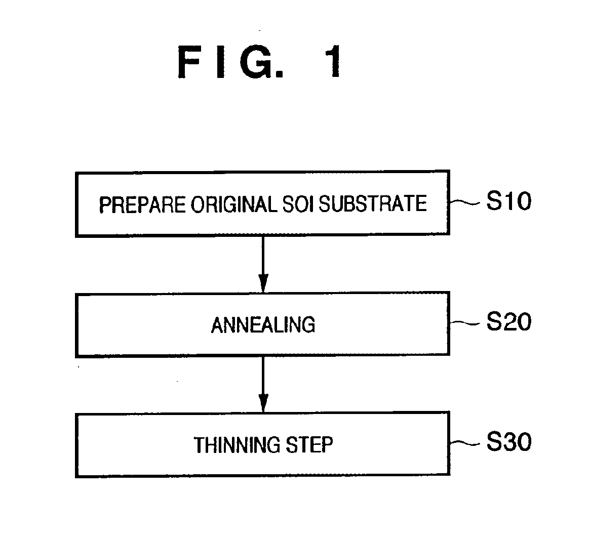
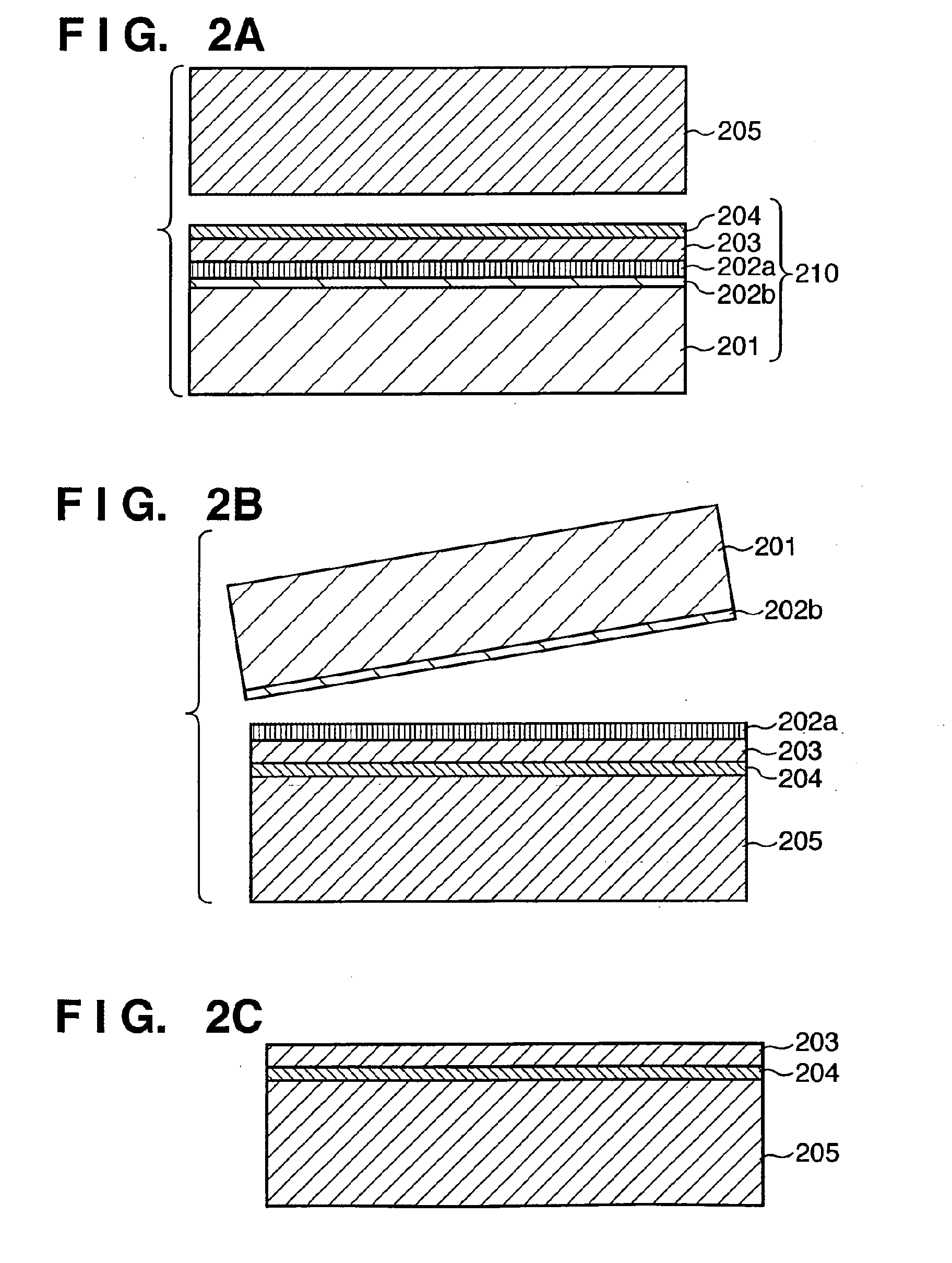
[0143] An original SOI substrate as schematically shown in FIG. 2C was formed using ELTRAN (registered trademark) (S10). The original SOI substrate was so formed as to have an SOI layer 203 with a thickness of 45 nm and a buried oxide film 204 with a thickness of 50 nm. The surface roughness of the original SOI substrate was measured at a 1-μm×1-μm region with an AFM. The resultant rms value was 10.5 nm.

[0144] The original SOI substrate was annealed (planarized) at 1,050° C. for 1 hr in a 100% hydrogen atmosphere (S20). The surface roughness of the SOI layer after the planarization was measured at a 1-μm×1-μm region with the AFM. It was confirmed that the surface roughness improved, i.e., the resultant rms value decreased to 0.09 nm. The film thickness of the SOI layer after the planarization was measured with an ellipsometer and was found to be 44 nm.

[0145] The original SOI subs...


PUM

PropertyMeasurementUnit
thicknessaaaaaaaaaa
thicknessaaaaaaaaaa
thicknessesaaaaaaaaaa

Abstract

An SOI substrate which has a thick SOI layer is first prepared. Then, the SOI layer is thinned to a target film thickness using as a unit a predetermined thickness not more than that of one lattice. This thinning is performed by repeating a unit thinning step which includes an oxidation step of oxidizing the surface of the SOI layer by the predetermined thickness not more than that of one lattice and a removal step of selectively removing silicon oxide formed by the oxidation. The SOI layer of the SOI substrate is chemically etched by supplying a chemical solution to the SOI layer, and the film thickness of the etched SOI layer is measured. When the measured film thickness of the SOI layer has a predetermined value, a process of chemically etching the SOI layer ends.

Description

[0001] This application is a division of application Ser. No. 10 / 841,621, filed May 10, 2004, which is incorporated herein by reference.FIELD OF THE INVENTION [0002] The present invention relates to a substrate manufacturing method and substrate processing apparatus and, more particularly, to a substrate manufacturing method suitable for manufacturing a substrate which has an Si layer with a precisely adjusted thickness on an insulating layer, and a substrate processing apparatus. BACKGROUND OF THE INVENTION [0003] A substrate which has an Si layer on an insulating layer is known as an SOI (Silicon On Insulator) substrate. As SOI substrate manufacturing methods, SIMOX (Separation by IMplantation of OXygen), bonding, and the like are known. [0004] SIMOX is a technique for implanting oxygen ions in an Si substrate at a predetermined depth and then annealing the substrate at a high temperature to form a buried silicon oxide layer. [0005] Bonding is a method of bonding the first substra...

Claims


Application Information

Patent Timeline
Patent Type & Authority Applications(United States)
IPC IPC(8): H01L21/30H01L21/46H01L21/00H01L21/306H01L21/3105H01L21/316H01L21/3213H01L21/66H01L21/762
CPCH01L22/12H01L22/20H01L21/30604H01L21/31056H01L21/76259H01L21/32134H01L21/6708H01L21/76254H01L21/31654H01L21/02164H01L21/02238E01D22/00E01D19/02
Inventor ITO, MASATAKAYAMAGATA, KENJIKAKIZAKI, YASUOTAKANASHI, KAZUHITOMIYABAYASHI, HIROSHIMORIWAKI, RYUJITSUBOI, TAKASHI
Owner CANON KK
Learn More