Woven or knitted fabric, diaphragm for speaker, and speaker

a diaphragm and fabric technology, applied in the direction of ceramic diaphragms, knitting, ornamental textile articles, etc., can solve the problem of elevated production costs, achieve excellent flexibility and bending properties, and produce at a low production cos

Inactive Publication Date: 2007-08-16
KB SEIREN LTD
View PDF3 Cites 48 Cited by
  • Summary
  • Abstract
  • Description
  • Claims
  • Application Information

AI Technical Summary

Benefits of technology

[0089] With respect to the woven/knitted fabric of the invention, having the above-mentioned constitution, the conductive fiber in the woven/knitted fabric forms the coil and therefore, the woven/knitted fabric can be used preferably for a diaphragm for a sp

Problems solved by technology

As described, conventionally, since a coil in a diaphragm for a speaker is to be formed by printing by a method of etching, met

Method used


Image

  • Woven or knitted fabric, diaphragm for speaker, and speaker
  • Woven or knitted fabric, diaphragm for speaker, and speaker
  • Woven or knitted fabric, diaphragm for speaker, and speaker

Examples


example 1

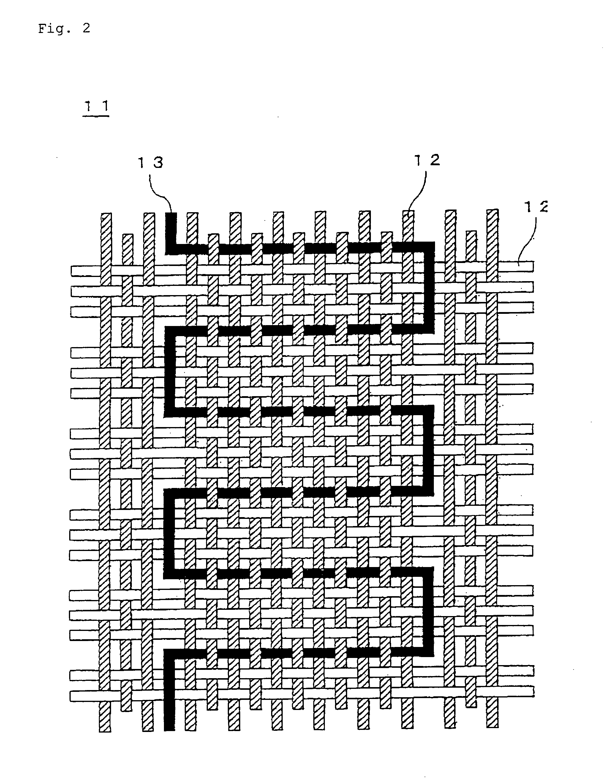
[0116] Parallel yarns each made of two polyester multifilaments with 33.3 dtex / 36 f (s900 (downward twisting) / z 600 (upward twisting)) were used as a warp and on the other hand, polyester multifilaments with 83.3 dtex / 72 f and a core-sheath structure fused yarn (83.3 dtex / 24 f) obtained by conjugating a polyester fiber having a melting point of 230° C. as a core material with a modified polyester having a melting point of 180° C. as a sheath material to form a thermally fusible layer on the surface of the core material were used as the weft at 1:1 and further as a portion of the weft, two parallel copper wires coated with a polyester and having a diameter of 0.1 mmφ were used and accordingly, a twill fabric in which a coil-like shape shown in FIG. 2 and FIG. 9 was formed was woven as a substrate. The piling number was 130 / 2.54 cm for the warp and 90 / 2.54 cm for the weft.

[0117] While being pinched from the upper side and the lower side by a clump with a disk shape having a hole with...

example 2

[0118] A woven fabric was produced in the same manner as Example 1, except that parallel yarns each made of two polyester multifilaments with 83.3 dtex / 72 f (s900 (downward twisting) / z 600 (upward twisting)) were used as a warp and polyester multifilaments with 83.3 dtex / 72 f (s300) and a core-sheath structure fused yarn (83.3 dtex / 24 f) obtained by conjugating a polyester fiber having a melting point of 230° C. as a core material with a modified polyester having a melting point of 180° C. as a sheath material to form a thermally fusible layer on the surface of the core material were used as the weft at 1:1 and further as a portion of the weft, two parallel copper wires coated with a polyester and having a diameter of 0.1 mmφ were used. The piling number was 166 / 2.54 cm for the warp and 90 / 2.54 cm for the weft. Weight of the twill fabric was 175 g / m2.

example 3

[0119] A woven fabric was produced in the same manner as Example 1, except that parallel yarns each made of two polyester multifilaments with 83.3 dtex / 72 f (s 900 (downward twisting) / z 600 (upward twisting)) were used as a warp and polyester multifilaments with 83.3 dtex / 72 f (s300) were used as the weft and further as a portion of the weft, two parallel copper wires coated with a polyester and having a diameter of 0.1 mmφ were used. The piling number was 166 / 2.54 cm for the warp and 90 / 2.54 cm for the weft. Weight of the twill fabric was 175 g / m2.


PUM

PropertyMeasurementUnit
Electrical conductoraaaaaaaaaa

Abstract

The invention aims to provide a woven/knitted fabric containing a conductive fiber preferably usable especially for a diagram for a speaker, and a diaphragm for a speaker and a speaker using the woven/knitted fabric. A woven/knitted fabric comprising a conductive fiber and a non-conductive fiber, wherein the woven/knitted fabric has a woven structure or a knitted structure of said non-conductive fiber and a continuous wiring forming a coil of the conductive fiber.

Description

FIELD OF THE ART [0001] The invention relates to a woven / knitted fabric, a diaphragm for a speaker, and a speaker. BACKGROUND ART [0002] A conventional flat type speaker is provided with a rod-type magnet and a diaphragm in which a coil is formed. This flat type speaker vibrates the diaphragm by applying alternating electric current to the respective portions of the coil and accordingly converts the electric signals into acoustic signals. As a diaphragm for a speaker installed to such a speaker, those which comprise a coil formed by printing on a diaphragm made of pulp, a thermoplastic resin film, a FRP (a fiber-reinforced plastic) or the like have been known (reference to Japanese Kokai Publication 2000-152378 and Japanese Kokai Publication 2003-299184). [0003] Japanese Kokai Publication 2000-152378 discloses a flat type acoustic-conversion apparatus in which a magnet, a coil, and a diaphragm have specified constitutions. With respect to this kind flat type acoustic-conversion appa...

Claims


Application Information

Patent Timeline
IPC IPC(8): D03D15/00B32B15/14D03D13/00D03D15/02D04B1/14H04R1/06H04R7/04H04R9/00
CPCD03D1/0088D03D13/00D03D15/02D04B1/14D10B2401/16H04R2499/13H04R7/04H04R2307/023H04R2307/025H04R2307/029H04R1/06D10B2403/02431Y10T442/3382Y10T442/475D03D21/00H04R9/00D03D15/533D03D15/25D10B2505/12D10B2101/20
Inventor SHIBAOKA, HIROSHITAKAHIRA, SUNAONINOMIYA, TATSUHIKOSHIBATA, EMIKO
Owner KB SEIREN LTD
Why Eureka
Try Eureka