
Oxidation catalyst for cleaning exhaust gas

a technology of oxidation catalyst and exhaust gas, which is applied in the direction of metal/metal-oxide/metal-hydroxide catalyst, physical/chemical process catalyst, separation process, etc., can solve the problems of insufficient function of oxidizing particulates and polycyclic aromatic hydrocarbons, and conventional composite oxides are not sufficient. achieve excellent function of oxidizing high boiling point materials

Inactive Publication Date: 2007-08-16
HONDA MOTOR CO LTD
View PDF2 Cites 5 Cited by
  • Summary
  • Abstract
  • Description
  • Claims
  • Application Information

AI Technical Summary

Benefits of technology

[0009]In view of such circumstances, an object of the present invention is to provide an oxidation catalyst for cleaning exhaust gas, excellent in the function of oxidizing high boiling point materials such as particulates and polycyclic aromatic hydrocarbons contained in the exhaust gas of internal-combustion engines.
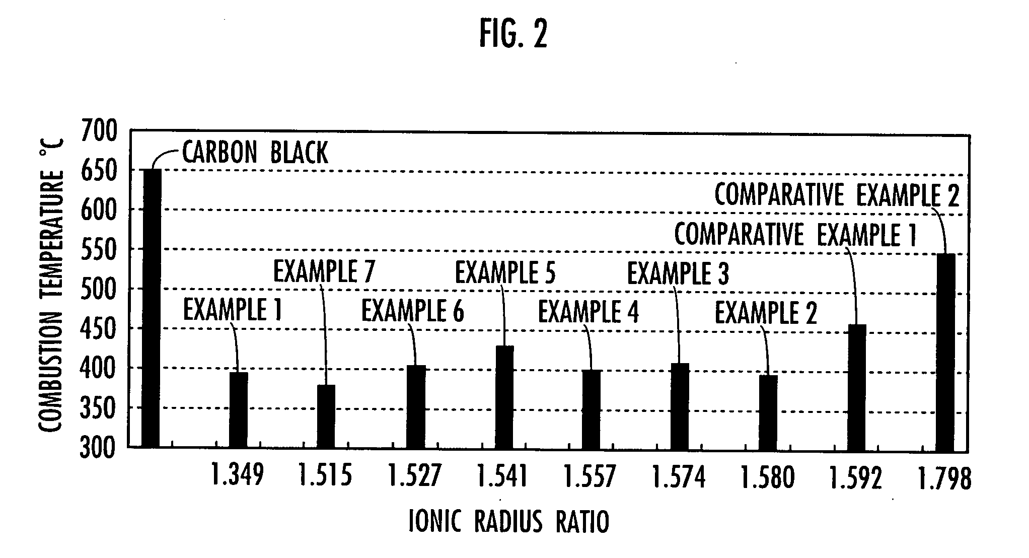
[0012]The oxidation catalyst for cleaning exhaust gas according to the invention can have a value of the ionic radius ratio between the two kinds of metal elements A and B (the ionic radius of metal element A) / (the ionic radius of metal element B) falling within the above-described range to make the composite oxide into a hexagonal structure to give an oxygen storage capacity more excellent than that of a composite oxide having a perovskite structure or a cerium-zirconium composite oxide. Thus, the oxidation catalyst for cleaning exhaust according to the invention can generate an extremely strong oxidation atmosphere in oxidizing high boiling point materials such as particulates and polycyclic aromatic hydrocarbons contained in the exhaust gas of internal-combustion engines, and enables the oxidation to be conducted at a temperature lower than before.

Problems solved by technology

The conventional oxidation catalyst for cleaning exhaust gas can oxidize volatile organic compounds (VOCs) having low boiling points contained in the above exhaust gas, but cannot achieve sufficient function for oxidizing the particulates and polycyclic aromatic hydrocarbons.
However, the conventional composite oxides are not sufficient in the function of oxidizing particulates, polycyclic aromatic hydrocarbons, and the like contained in the above-described exhaust gas, and desired to be further improved.

Method used


Image

  • Oxidation catalyst for cleaning exhaust gas
  • Oxidation catalyst for cleaning exhaust gas

Examples


example 1

[0028]In this Example, the acetate or nitrate of manganese was first added to the acetate or nitrate of scandium into a molar ratio of Sc:Mn=1:1, to which urea was further added into a molar ratio of Sc:Mn:N2H4CO=1:1:6, followed by grind mixing. Next, the resultant mixture was allowed to react at 250° C. for 30 minutes, then at 300° C. for 30 minutes, and further at 350° C. for one hour. After the end of reaction, the resultant mixture was subsequently grind mixed, followed by calcining at 800° C. for one hour to provide a composite oxide.

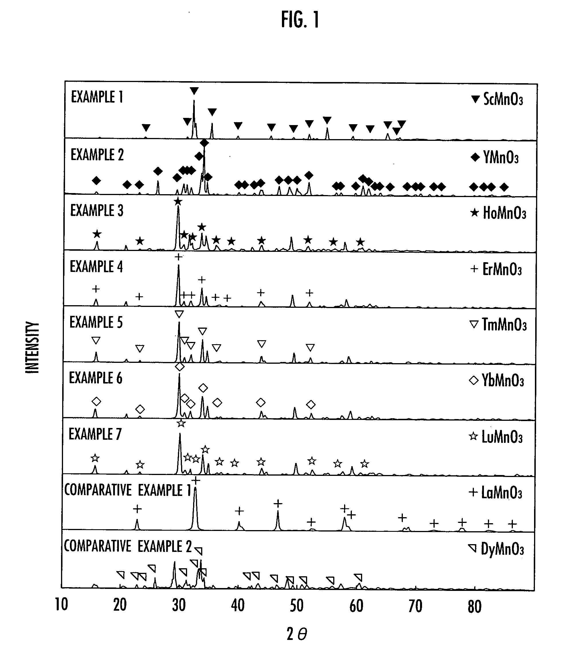
[0029]To ascertain the crystal structure of the composite oxide obtained in this Example, the X-ray diffraction pattern thereof was then measured. The measurement was carried out under conditions of tube voltage: 50 kV, tube current: 150 mA, diffractometer: 4° / minute, and measuring range (2θ): 10 to 900 using an X-ray diffractometer from Burker. As a result, it turned out that the crystal obtained in this Example was ScMnO3 having a hexagonal struc...

example 2

[0032]In this Example, a composite oxide was first obtained just as described in Example 1 except for the use of the acetate or nitrate of yttrium instead of the acetate or nitrate of scandium.

[0033]To ascertain the crystal structure of the composite oxide obtained in this Example, the X-ray diffraction pattern thereof was then measured just as described in Example 1. As a result, it turned out that the crystal obtained in this Example was YMnO3 having a hexagonal structure. The ionic radius ratio between Y and Mn (the ionic radius of Y / the ionic radius of Mn) was 1.580. The X-ray diffraction pattern is shown in FIG. 1.

[0034]To evaluate the oxidation property of the composite oxide obtained in this Example for particulates, the composite oxide was then mixed with carbon black, followed by performing the thermal analysis of carbon black just as described in Example 1. The mixture of the composite oxide obtained in this Example and carbon black had a combustion peak temperature of 390...

example 3

[0035]In this Example, a composite oxide was first obtained just as described in Example 1 except for the use of the acetate or nitrate of holmium instead of the acetate or nitrate of scandium.

[0036]To ascertain the crystal structure of the composite oxide obtained in this Example, the X-ray diffraction pattern thereof was then measured just as described in Example 1. As a result, it turned out that the crystal obtained in this Example was HoMnO3 having a hexagonal structure. The ionic radius ratio between Ho and Mn (the ionic radius of Ho / the ionic radius of Mn) was 1.574. The X-ray diffraction pattern is shown in FIG. 1.

[0037]To evaluate the oxidation property of the composite oxide obtained in this Example for particulates, the composite oxide was then mixed with carbon black, followed by performing the thermal analysis of carbon black just as described in Example 1. The mixture of the composite oxide obtained in this Example and carbon black had a combustion peak temperature of ...


PUM

PropertyMeasurementUnit
Radiusaaaaaaaaaa

Abstract

An oxidation catalyst for cleaning exhaust gas, excellent in the function of oxidizing high boiling point materials such as particulates and polycyclic aromatic hydrocarbons contained in the exhaust gas of internal-combustion engines is provided. The catalyst is a composite oxide containing two kinds of metal elements, wherein, when the two kinds of metal elements are defined as A and B, the value of the ionic radius of metal element A / the ionic radius of metal element B is in the range of from 1.349 to 1.580. The metal element A is selected from the group consisting of Sc, Y, Ho, Er, Tm, Yb, and Lu, and the metal element B is Mn. The composite oxide has a hexagonal structure.

Description

BACKGROUND OF THE INVENTION[0001]1. Field of the Invention[0002]The present invention relates to an oxidation catalyst for cleaning exhaust gas, which oxidizes particulates, polycyclic aromatic hydrocarbons and the like contained in the exhaust gas discharged from internal-combustion engines to clean the exhaust gas.[0003]2. Description of the Related Art[0004]In order to clean the exhaust gas discharged from internal-combustion engines such as a motorcar engine, an oxidation catalyst for cleaning exhaust gas in which a noble metal as a catalyst is supported on a heat-resistant carrier such as alumina, and ceria or the like is further mixed to promote oxidation reaction has been conventionally used. The conventional oxidation catalyst for cleaning exhaust gas can oxidize volatile organic compounds (VOCs) having low boiling points contained in the above exhaust gas, but cannot achieve sufficient function for oxidizing the particulates and polycyclic aromatic hydrocarbons.[0005]This i...

Claims


Application Information

Patent Timeline
IPC IPC(8): B01J23/00B01J23/32
CPCB01D53/945B01D2255/206B01J23/002B01J23/10B01J23/34B01J35/002B01J2523/00Y02T10/22B01J2523/3793B01J2523/72B01J2523/3781B01J2523/3775B01J2523/3768B01J2523/3787B01J2523/35B01J2523/36Y02T10/12B01J35/30
Inventor ISOGAI, YUJITANAAMI, KIYOSHIONODERA, MINAKONAKA, TAKAHIRO
Owner HONDA MOTOR CO LTD
Learn More