Continuous process for producing poly(trimethylene terephthalate)

a technology of triethylene terephthalate and continuous process, which is applied in the direction of piezoelectric/electrostrictive transducers, instruments, transducer types, etc., can solve the problems of poor spraying operation, poor quality of the spraying condenser, and low flow rate of 1,3-propanediol recirculation, so as to reduce the amount of fouling and excellent quality

Inactive Publication Date: 2007-08-16
DUPONT IND BIOSCIENCES USA LLC
View PDF15 Cites 30 Cited by
  • Summary
  • Abstract
  • Description
  • Claims
  • Application Information

AI Technical Summary

Benefits of technology

[0030] Thus, the invention provides a continuous poly(trimethylene terephthalate) polymerization process wherein it is possible to recycle liquid by-product 1,3-propanediol into the process without purification of the recycle stream, while at the same time obtaining excellent quality poly(trimethylene terephthalate). According to preferred embodiments, this can be done while substantially reducing the amount of fouling due to precipitation of solids from the liquid by-product 1,3-propanediol.

Problems solved by technology

The precipitates may cause fouling, which in turn results in lower 1,3-propanediol recirculation flow rates and eventual poor spray condenser operation.
This buildup of solids in the recirculation system leads to shortened operational life, increased maintenance frequency and, consequently, higher costs due to increased downtime, maintenance costs and lower overall product yields.
These problems in recycle of 1,3-propanediol have resulted in reports (see, e.g., U.S. Pat. No. 6,657,044) that it is necessary to remove the solid by-products from the recovered by-product 1,3-propanediol in order to successfully recycle it.

Method used


Image

  • Continuous process for producing poly(trimethylene terephthalate)

Examples


example 1

[0072] This example demonstrates preparation of high quality poly(trimethylene terephthalate) in a continuous process where the condensed by-product 1,3-propanediol and other by-products are recycled back to the esterification reaction without purification.

[0073] A self-circulating esterifier designed as described in U.S. Pat. No. 3,927,982 was operated at about 245° C. and a process pressure of between 4 and 5 psig (129 to 136 kPa). Fresh 1,3-propanediol was continuously loaded into a 500 lb (227 kg) capacity feed tank from which it was fed to make paste. A paste containing fresh 1,3-propanediol and terephthalic acid at a mole ratio of about 1.5 (35.5 kg / h terephthalic acid and 24.4 kg / h 1,3-propanediol), and TYZOR® TPT catalyst at a level of 33 ppm Ti (relative to final polymer) was continually injected into the esterifier at a polymer production rate of 44.1 kg / h (97 lb / h). Water and 1,3-propanediol vapors were continually extracted into a distillation column where the water and...

examples 4-7

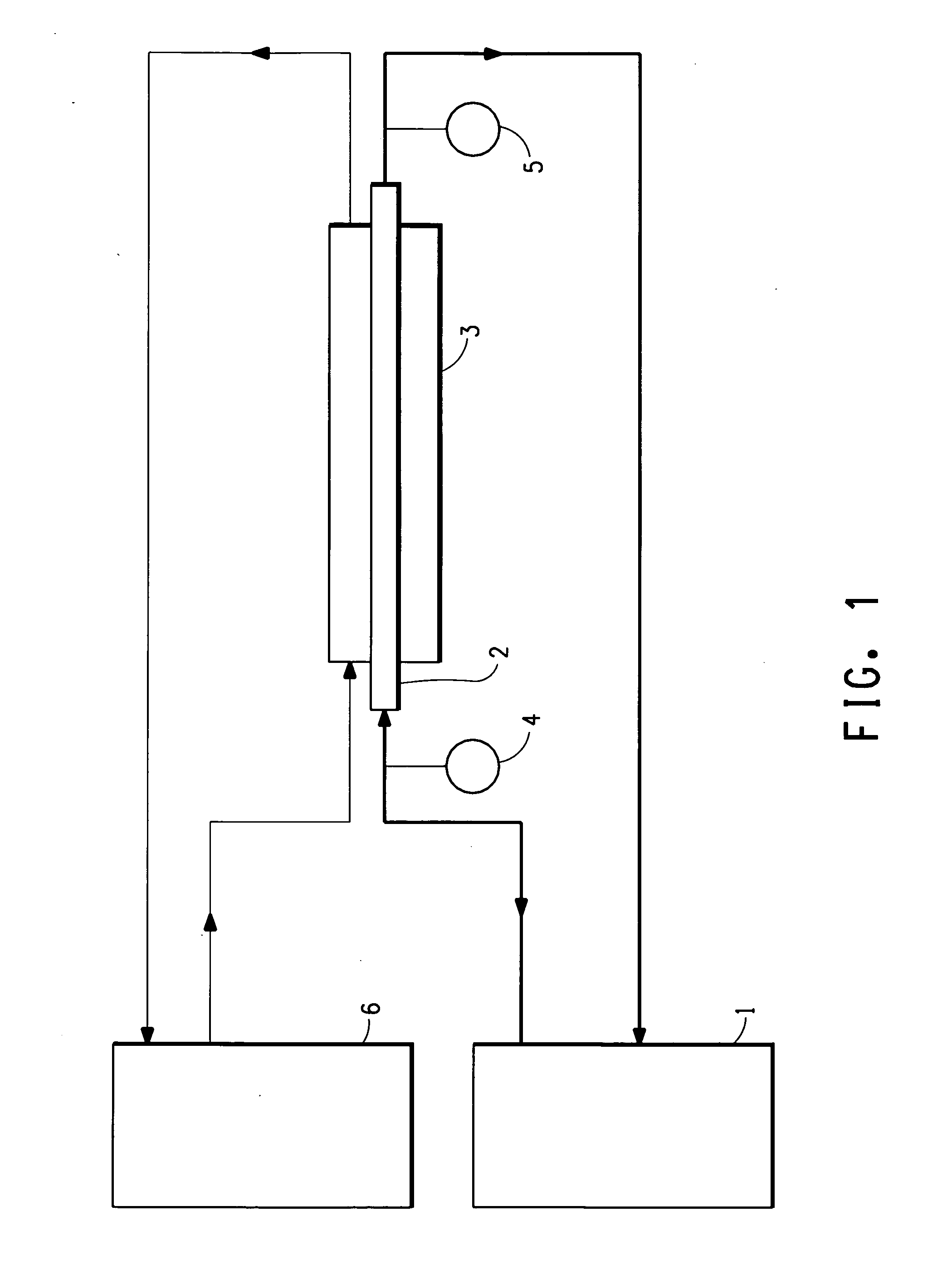
[0083] These examples were carried out with an apparatus utilizing a 5 / 32 inch inner diameter outlet tube 2 instead of the 0.25 inch outlet tube used in Examples 2 and 3. It was therefore expected that the effect of fouling on flow restriction should be greater in these examples than in the previous ones. The results are in Table 2.

TABLE 2Exp. 4Exp. 5Exp. 6Exp. 7Wt % Cyclic Dimer1.01.01.55.0Inlet Temp. (° C.)49.945.050.045.5Initial Outlet Temp. (° C.)47.042.046.041.5Test Duration (Hrs.)24242424Final Outlet Temp. (° C.)45.541.145.440.7Outlet Temp. Drop (° C.)1.50.90.60.8

[0084] As expected, the effect of the lower diameter tube in these examples was to somewhat increase the observed outlet temperature drop. However, comparison of the results of Examples 5, 6 and 7 to those of Example 4 indicate that when the circulation temperature was less than about 50° C., the amount of precipitation / fouling was less than it was at about 50° C. as evident from the temperature drops. Thus, in addi...


PUM

PropertyMeasurementUnit
temperatureaaaaaaaaaa
pressureaaaaaaaaaa

Abstract

This invention relates to a continuous process for production of poly(trimethylene terephthalate), wherein gaseous 1,3-propanediol by product resulting from the process is condensed in a condenser, and a portion of the condensed by-product is recycled back into the process.

Description

CROSS-REFERENCE TO RELATED APPLICATIONS [0001] This application claims priority under 35 U.S.C. §119 from Provisional Application No. 60 / 752,479 (filed Dec. 21, 2005), the disclosure of which is incorporated by reference herein for all purposes as if fully set forth. [0002] This application is related to application Ser. No. ______ (filed concurrently herewith), entitled “CONTINUOUS MANUFACTURE OF POLY(TRIMETHYLENE TEREPHTHALATE)”, which claims priority under 35 U.S.C. §119 from Provisional Application No. 60 / 752,481 (filed Dec. 21, 2005); and application Ser. No. ______ (filed concurrently herewith), entitled “POLY(TRIMETHYLENE TEREPHTHALATE) CONTINUOUS MANUFACTURING PROCESS”, which claims priority under 35 U.S.C. §119 from Provisional Application No. 60 / 752,318 (filed Dec. 21, 2005); the disclosures of which are incorporated by reference herein for all purposes as if fully set forth.FIELD OF THE INVENTION [0003] This invention relates to a continuous process for production of poly...

Claims


Application Information

Patent Timeline
Patent Type & Authority Applications(United States)
IPC IPC(8): C08G63/02
CPCC08G63/183Y10T29/49005C08G63/78C12Q1/22G01N33/569
Inventor ENG, JOHN HARVEYBLUM, EMILY A.GREEN, DANIEL ALBERTGIARDINO, CARL J.PARRISH, GENETROTTER, ROBERT E.WILSON, GARY J.
Owner DUPONT IND BIOSCIENCES USA LLC
Why Eureka
Try Eureka