Methane conversion to higher hydrocarbons

a technology of methane and acetylene, which is applied in the direction of hydrocarbon by hydrocarbon cracking, liquid gas reaction process, energy input, etc., can solve the problems of high cost, high cost, and inability to scale well, and achieve efficient conversion of methane , the effect of avoiding equipment heat degradation

Active Publication Date: 2007-08-16
EXXONMOBIL CHEM PAT INC
View PDF83 Cites 184 Cited by
  • Summary
  • Abstract
  • Description
  • Claims
  • Application Information

AI Technical Summary

Benefits of technology

[0019] The present inventors have discovered that acetylene can be efficiently manufactured from methane feed according to the inventive reverse-flow regenerative reactor system, method, and process. This invention provides processes and apparatus for efficiently converting methane by controlling location, movement, and removal of reaction heat. The inventive process beneficially feeds all of the exothermically reacting regeneration reactant streams through the recuperation or quenching reactor bed media, while simultaneously deferring combustion, until the reactants reach a desired region of the reactor system. The invention also includes use of an inventive mixing apparatus within the high heat region to provide efficient and complete mixing and exothermic reaction within the reactor system. The inventive process also preferably utilizes hydrogen as a methane synthesis reaction diluent. The inventive process creates and confines a regenerating “heat bubble” within the reactor system, without exposing any degradable components to the high heat. The inventive process consistently provides controlled exothermic reaction location and temperature migration and successfully avoids equipment heat degradation.

Problems solved by technology

Acetylene (or ethyne, HC≡CH) has long been recognized as one of the few compounds that can be made directly at high selectivity from methane but the conditions of that manufacture have placed it beyond commercial practicality for other than high cost, specialty production.
One of the biggest impediments to producing acetylene from methane feeds has been the very high temperatures required to produce high-yield conversion of methane to acetylene.
Pyrolyzing large quantities of methane had been considered much too costly and impractical due to the special types and costs of equipment that would be required.
However, the known processes are inefficient, do not scale well, and are generally only useful for specialty applications.
Such temperature and processes have largely been unattractive due to the degradation of the equipment utilized.
Virtually any metal components that are exposed to such temperatures will be costly and will unacceptably degrade.
This publication indicates that the use of these furnaces permits substantial increases in the yield of olefins (i.e., ethylene, propylene, butadiene) while decreasing production of less-desirable co-products.
It is believed that all commercial acetylene plants operated on feeds of ethane, naphtha, and / or butane, but that none have successfully operated on methane feeds.
However, this also exposes the lateral injection nozzles or ports to the combustion product, including the extremely high temperature needed to crack methane feeds.
Degradation in nozzle performance, shape, and / or size consequently made it extremely difficult to control flame shape, temperature, and efficiency.
Although some of the Wulff art disclose use of various refractory materials, a commercially useful process for methane cracking was not achieved utilizing such materials.
Also, a further drawback of the Wulff process is that the laterally or separately introduced portion of exothermic reactant is not utilized for quenching the recuperation reactor bed.
Although this may defer or control location of combustion, that process limits the cooling of the quench regions of the reactor, due to not having that stream pass through regenerative beds or regions.
This can result in expanding heat zones loss of reaction control.
In large scale operations, such methods are impermissibly inefficient and costly.
All of these previously known systems suffer disadvantages that render the same inefficient and unpractical in any but very specialized, small scale operations with methane feeds.
Positioning nozzles, distributors, or burners in the middle of the regenerative flow path of the reactor diminishes the durability and control of the reactor system.
It is very difficult to fabricate and maintain carefully-dimensioned shapes for use at high temperatures.
If the nozzles or distributor loses its carefully-dimensioned shape, it will no longer produce uniform flame temperatures.
A further disadvantage of separately or laterally introducing one or more reactant directly into the middle or heat region of the regenerative flow path of the reactor is that such an arrangement bypasses that reactant around the regenerative flow path.
Bypassing some fraction of the feed to the reactor around the regenerative system thus reduces the efficiency potential of the reactor system and can lead to expanded heat zones and feed conversion reactions that last too long.
All of the known art disclose processes, methods, and equipment that are unsuitable for continuous, high efficiency operation at the necessarily high temperature, due to complexity and thermal degradation of equipment.
Also, the known processes do not reliably provide methods or means for continuously controlling the location and dissipation of the created heat, resulting in either hot spots, undesired thermal migration, and / or inefficient processes.

Method used


Image

  • Methane conversion to higher hydrocarbons
  • Methane conversion to higher hydrocarbons
  • Methane conversion to higher hydrocarbons

Examples


example 1

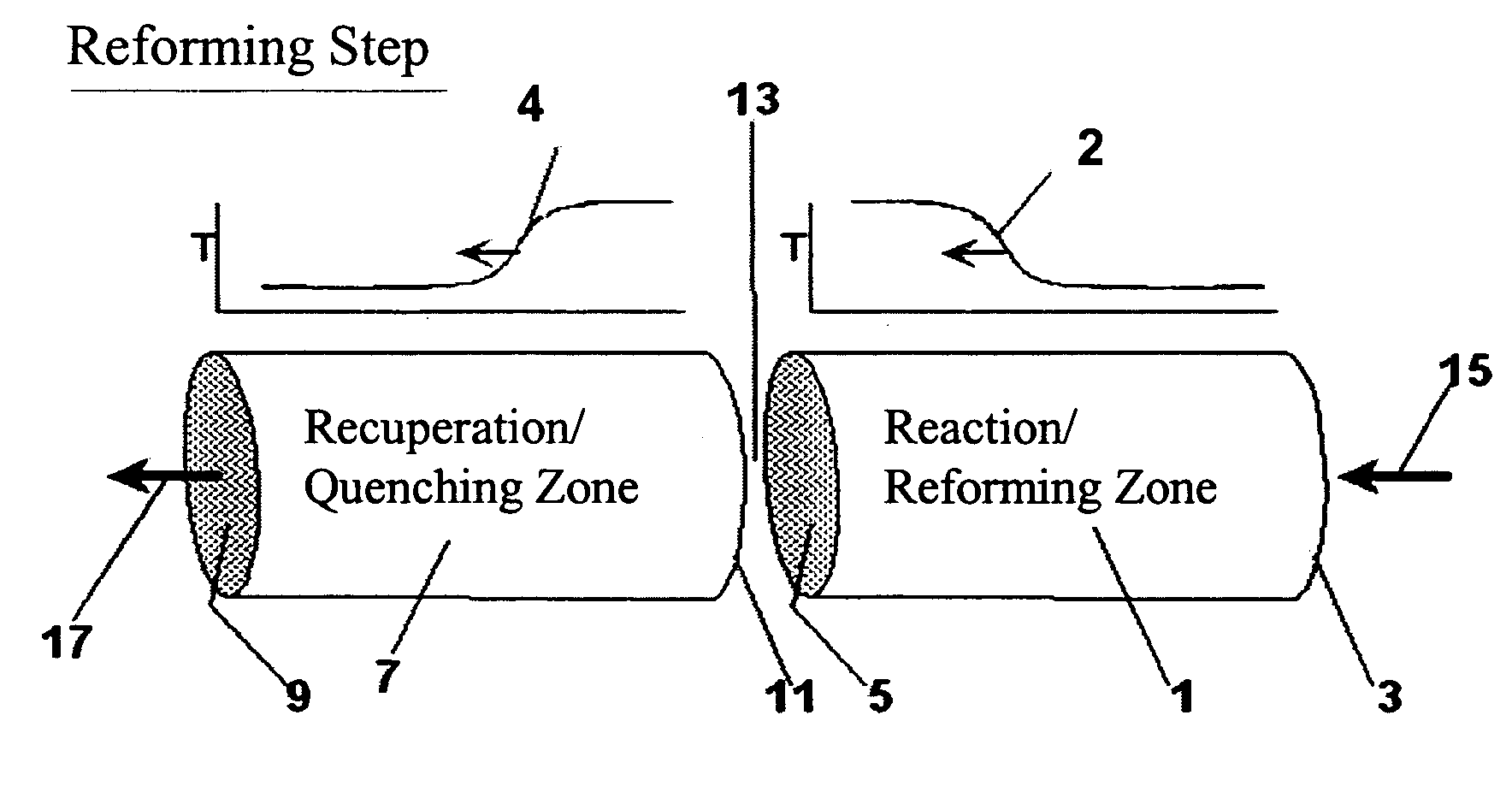
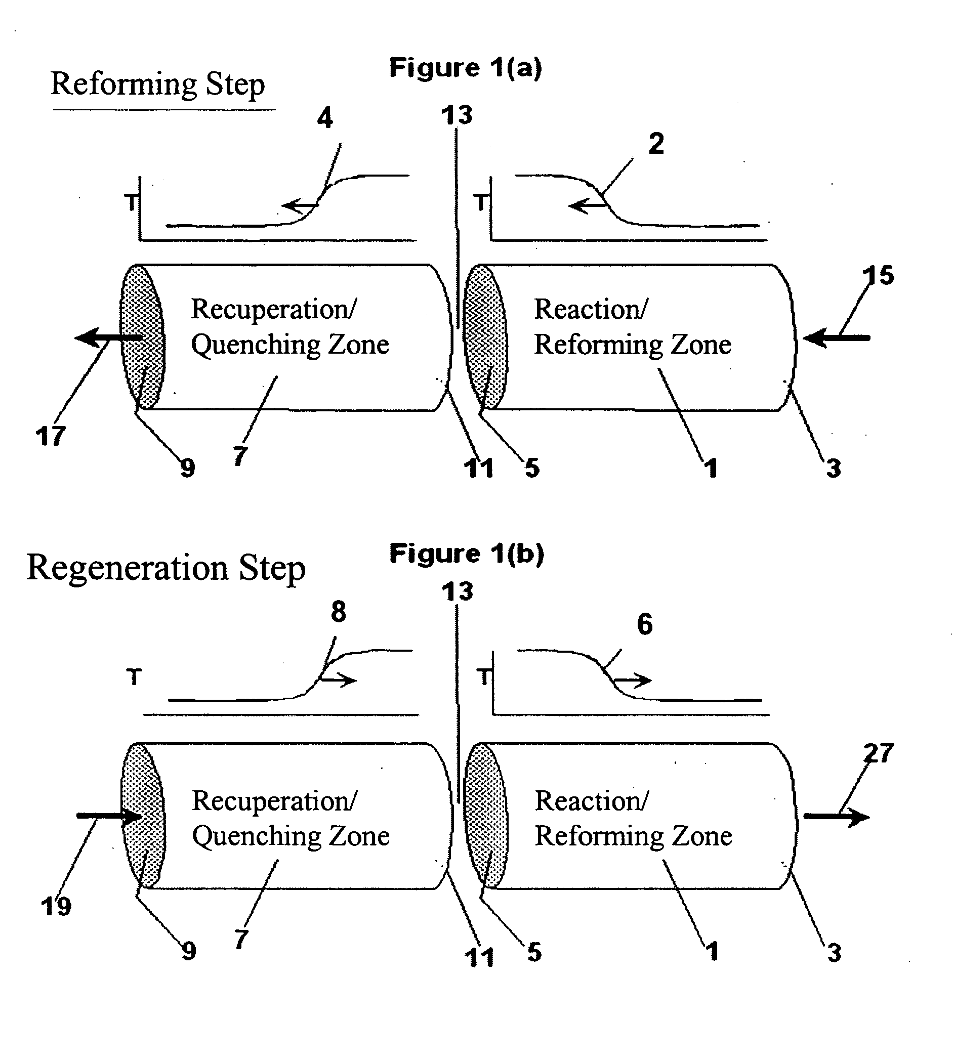
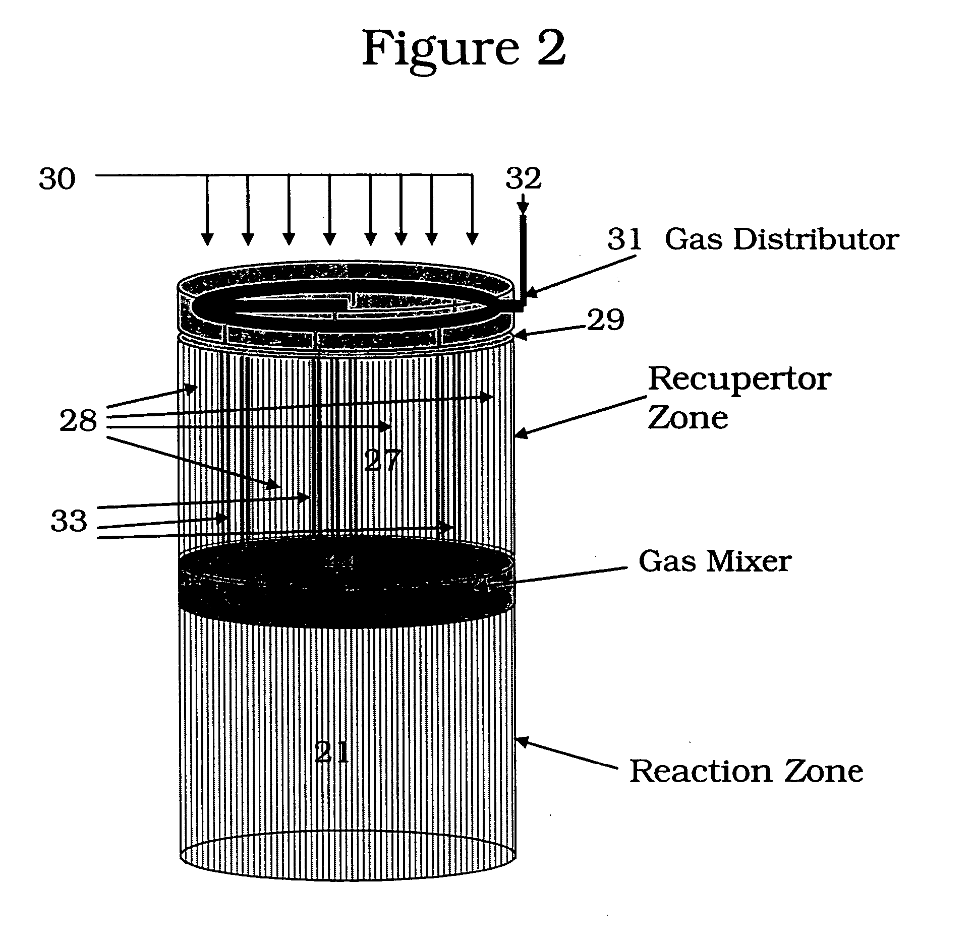
[0110] The following example is merely illustrative of one exemplary embodiment and process, and is not intended to limit the scope of the invention. Methane is converted to acetylene in a pair of reactor systems, each arranged according to simplified illustration FIG. 5, suitably valved, such that one reactor system is executing the regeneration step while the other reactor system is executing the pyrolysis step. Some embodiments may also include more reactor systems than just a pair, such as multiple reactor systems, each operating in a phased timing arrangement, such that the entire process is substantially continuous. The reactor system includes at least a first reactor / recuperator (102), a mixer or mixing zone (109), and a second reactor / reforming zone (101).

[0111] Both reforming (101) and recuperation (102) reactor zones comprise extruded, ceramic honeycomb monolith blocks, stacked in 3 dimensions to fill the reactor zone volume. The overall reactor systems are about 10 ft in...


PUM

PropertyMeasurementUnit
temperaturesaaaaaaaaaa
temperatureaaaaaaaaaa

Abstract

The present invention provides a process for the manufacture of acetylene and other higher hydrocarbons from methane feed using a reverse-flow reactor system, wherein the reactor system includes (i) a first reactor and (ii) a second reactor, the first and second reactors oriented in a series relationship with respect to each other, the process comprising supplying each of first and second reactant through separate channels in the first reactor bed of a reverse-flow reactor such that both of the first and second reactants serve to quench the first reactor bed, without the first and second reactants substantially reacting with each other until reaching the core of the reactor system.

Description

RELATIONSHIP TO RELATED APPLICATIONS [0001] This application claims benefit of and priority to U.S. Provisional Application No. 60 / 753,961, filed Dec. 23, 2005, and benefit of related US Non-Provisional Application No. (Serial number not yet assigned), titled “Controlled Combustion for Regenerative Reactors,” filed on Dec. 15, 2006, as the assignee's Family No. P2005J047-US2, the entirety of both of which are incorporated herein by reference.FIELD OF THE INVENTION [0002] The invention relates to the manufacture of acetylene from methane. The present invention also relates broadly to regenerative reactors. More particularly the invention relates to an improved process and apparatus for producing acetylene from a methane feed by controlling combustion for thermal regeneration of reverse flow regenerative reactors in a unique and thermally efficient way. BACKGROUND OF THE INVENTION [0003] Acetylene (or ethyne, HC≡CH) has long been recognized as one of the few compounds that can be made...

Claims


Application Information

Patent Timeline
Patent Type & Authority Applications(United States)
IPC IPC(8): C07C4/02C07C11/00C07C2/02B01J12/00
CPCB01F3/02C07C2/78B01F2215/0431B01J4/002B01J8/02B01J8/0278B01J8/04B01J8/0438B01J8/0442B01J8/0492B01J8/0496B01J19/2485B01J19/26B01J2208/00132B01J2208/00309B01J2208/00504B01J2208/0053B01J2208/00831B01J2208/0084B01J2208/00849B01J2219/0004B01J2219/00081B01J2219/00117B01J2219/00157B01J2219/00159B01J2219/182B01J2219/1943C01B3/46C01B2203/0233C01B2203/0238C01B2203/0244C01B2203/0261C01B2203/0277C01B2203/0811C01B2203/0844C01B2203/1235C01B2203/1241C01B2203/142C07C5/327C08G18/10C08G18/4825C08G18/73C08G18/792C08G2101/005B01F5/0603Y10S585/943C07C11/24C08G18/3203C08G18/48Y02P20/129C08G2110/005B01F23/10B01F25/421
Inventor HERSHKOWITZ, FRANKBUCHANAN, JOHN SCOTTDECKMAN, HARY W.FREDERICK, JEFFREY W.
Owner EXXONMOBIL CHEM PAT INC
Why Eureka
Try Eureka