Multi-color illuminating device and projection type video display

Inactive Publication Date: 2007-08-23
SANYO ELECTRIC CO LTD
View PDF6 Cites 24 Cited by
  • Summary
  • Abstract
  • Description
  • Claims
  • Application Information

AI Technical Summary

Benefits of technology

[0021] According to the present invention, there is an effect that can reduce generation of the difference in the illuminance distribution, the divergence angle distribution, and the divergence angle distribution within surface in each light in respe

Problems solved by technology

In a known optical system, however, uniformly raisi

Method used


Image

  • Multi-color illuminating device and projection type video display
  • Multi-color illuminating device and projection type video display
  • Multi-color illuminating device and projection type video display

Examples


embodiment 1

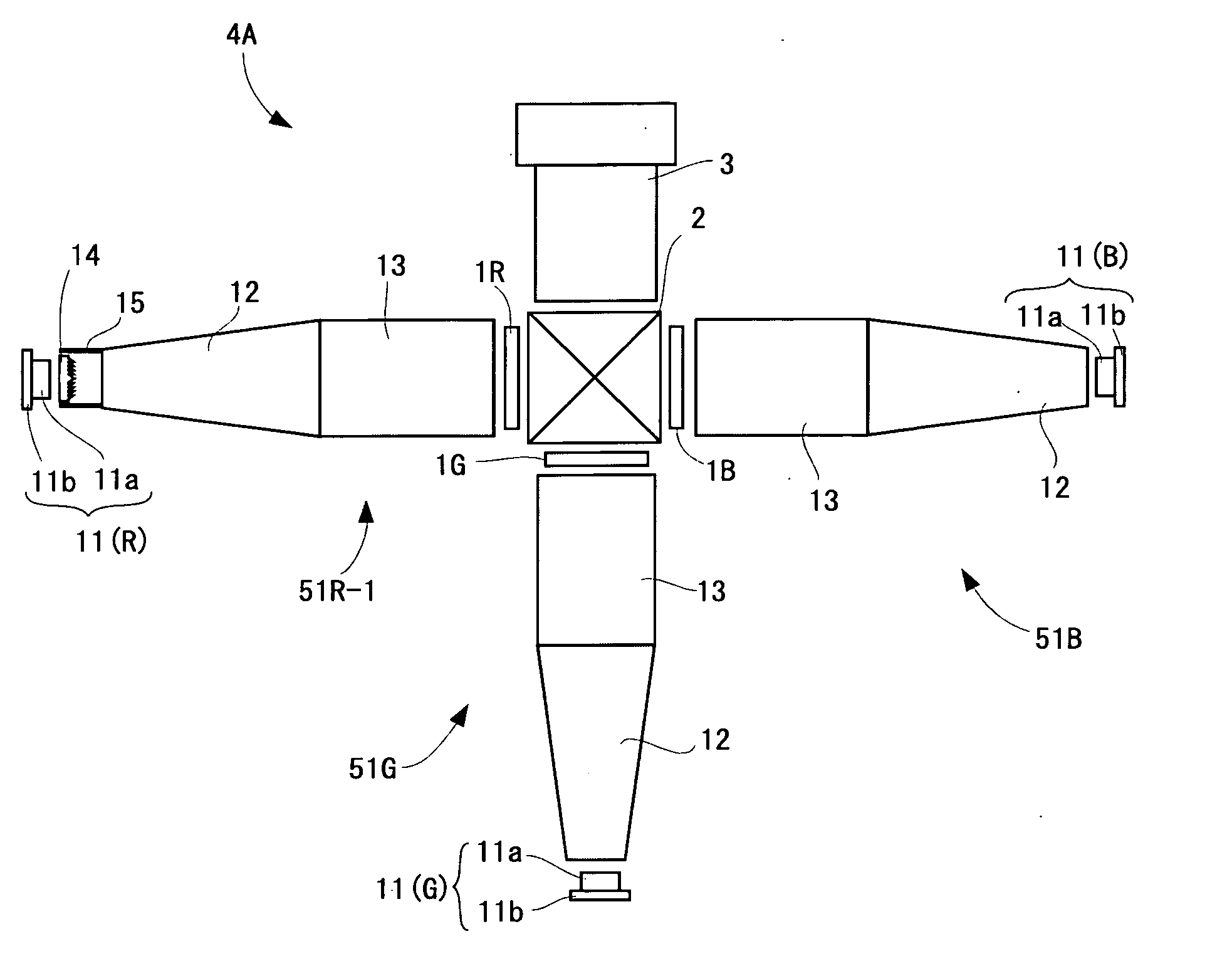
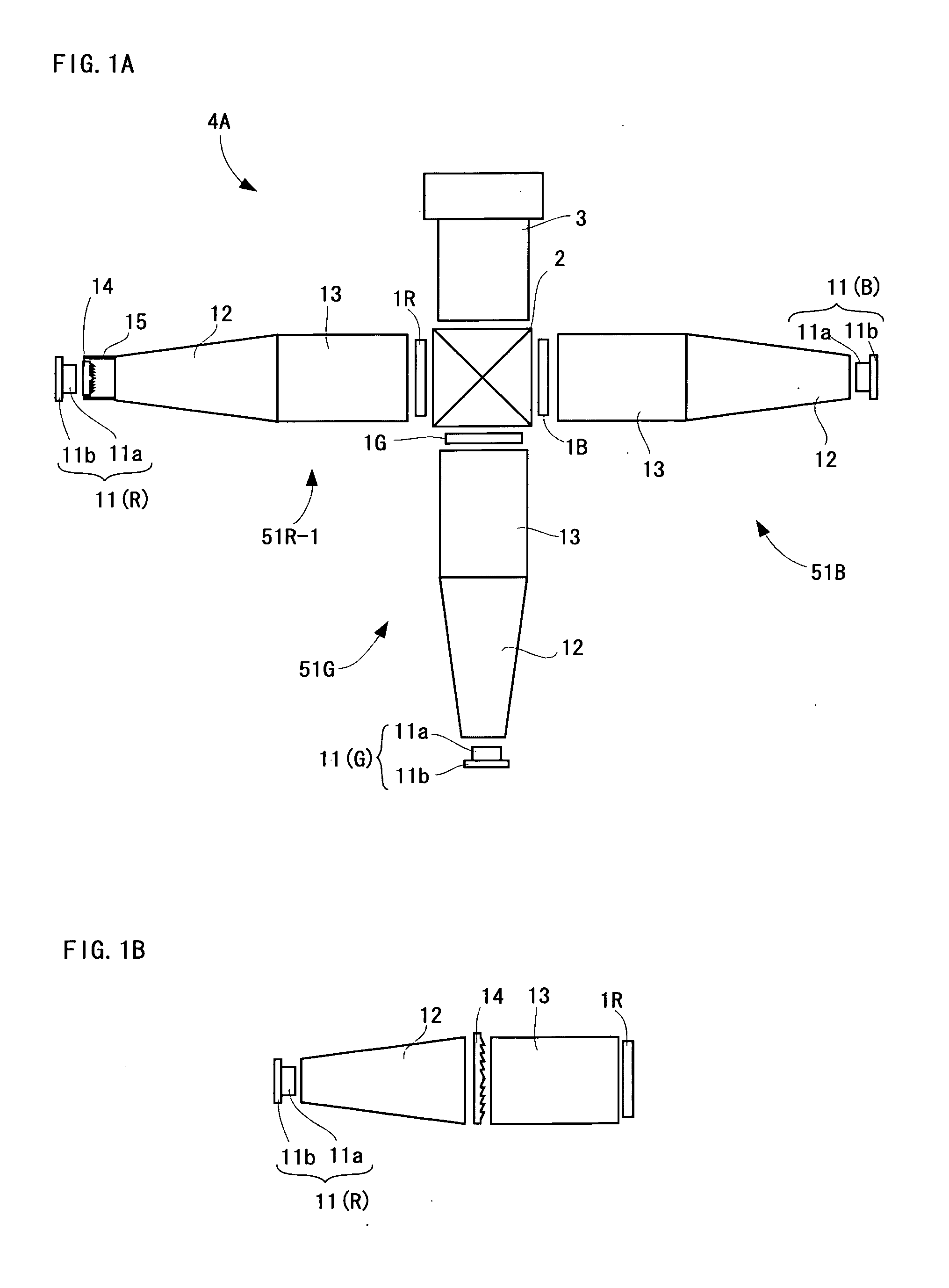
[0039]FIG. 1A is a view showing an optical system of a projection type video display 4A. The projection type video display 4A includes three illuminating devices 51R-1, 51G, and 51B. Each illuminating device 51 includes an LED (light-emitting diode) 11, a taper type rod integrator 12, and a cuboid shaped rod integrator 13.

[0040] The LED 11 is composed of an LED chip 11a and a heat sink 11b. The LED chip 11a in the illuminating device 51R-1 emits red light, the LED chip 11a in the illuminating device 51G emits green light, and the LED chip 11a in the illuminating device 51B emits blue light.

[0041] Each light in respective colors emitted from each illuminating device 51 passes through liquid crystal display panels 1R, 1G, and 1B for respective colors, thereby forming each color image light. Then, respective color image lights are combined by a cross dichroic prism 2 (a cross dichroic mirror may be used) to form full color image light. The full color image light is projected by a pro...

embodiment 2

[0045]FIG. 3A is an enlarged view showing a part of an illuminating device 51R-2 (a rod integrator 13 is omitted); and FIG. 3B is an enlarged view showing a part of an illuminating device 51R or 51G (the rod integrator 13 is omitted). The whole configuration as a projection type video display is the same as the projection type video display 4A. A shape of a light emission surface of the taper type rod integrator 12 is, for example, the same or the substantially the same as an aspect ratio of the liquid crystal display panel 1 (a horizontal width is denoted by c in the drawing). A shape of the light incident surface of a taper type rod integrator 12A is also, for example, the same or the substantially the same as the aspect ratio of the liquid crystal display panel 1.

[0046] In this case, when a horizontal width of the light incident surface of the taper type rod integrator 12 in the illuminating devices 51G or 51B is denoted by b and a horizontal width of the light incident surface ...

embodiment 3

[0047]FIG. 4A is an explanation view showing a projection type video display 4B. A configuration as the whole of the projection type video display 4B is the same as the projection type video display 4A. FIG. 4B is an explanation view showing an illuminating device 51R-3 and effect of reducing a divergence angle caused by a curved surface. A taper type rod integrator 12B in the illuminating device 51R-3 has a curved surface reflecting region which is more convex than an inclined reflecting surface in other taper type rod integrators 12. The nearer the tangential line of the curved surface in the curved surface reflecting region places to a light incident surface, the larger the angle with respect to an optical axis of the taper type rod integrator 12B becomes; whereas the farther the tangential line places from the light incident surface, the smaller the angle with respect to the optical axis becomes. Thereby, the rod integrator 12B receives light in a divergence angle coverage of −3...


PUM


Abstract

The projection type video display includes three illuminating devices (51R-1, 51G, and 51B). Each illuminating device includes a taper type rod integrator and a cuboid shaped rod integrator. The illuminating device (51R-1) emits red light; the illuminating device (51G) emits green light; and the illuminating device (51B) emits blue light. The illuminating device (51R-1) has a Fresnel lens. The illuminating devices (51G and 51B) do not have a Fresnel lens.

Description

BACKGROUND OF THE INVENTION [0001] 1. Field of the Invention [0002] The present invention relates to a multi-color illuminating device and a projection type video display. [0003] 2. Description of the Related Art [0004] In a projector's light source, the higher a parallelism of light from a light source is, the higher light use efficiency in an optical system becomes, therefore it is of advantage to raise directivity of an LED (light-emitting diode). Therefore, LED directivity is improved using a molded lens, a photonic crystal, and the like (refer to Japanese Unexamined Patent Publication No. 2005-149943). SUMMARY OF THE INVENTION [0005] In a known optical system, however, uniformly raising directivity of each color LED has been difficult. For example, as shown in FIG. 15A and FIG. 15B, a red LED has higher light intensity in a divergence angle coverage from −30° to −60° and in a divergence angle coverage from 30° to 60° than that of a green LED and a blue LED (for example, refer t...

Claims


Application Information

Patent Timeline
IPC IPC(8): G03B21/26
CPCG03B21/208G03B21/2033
Inventor YOKOTE, YOSHIHIROAMANO, RYUHEIARAI, KAZUHIROKUROSAKA, YOSHITAKAMAEDA, MAKOTOIKEDA, TAKASHIMURATA, HARUHIKO
Owner SANYO ELECTRIC CO LTD
Why Eureka
Try Eureka