Triple voltage DC-to-DC converter and method

a dc-to-dc converter and triple voltage technology, applied in the direction of hybrid vehicles, process and machine control, instruments, etc., can solve the problems of increasing volume and cost, increasing power losses in switches and inductor, and/or the size and volume of filter capacitors, etc., to relieve the burden of carrying a large current, reduce the burden of volume and power loss, and reduce the effect of voltage fluctuations

Inactive Publication Date: 2007-08-23
UT BATTELLE LLC
View PDF1 Cites 51 Cited by
  • Summary
  • Abstract
  • Description
  • Claims
  • Application Information

AI Technical Summary

Benefits of technology

[0008] The present invention provides a dc-to-dc converter circuit that not only fulfills all of the requirements aforementioned but solves the problems encountered with the prior art. It offers improvements in terms of reduced cost, volume and power losses by moving the 14-volt bus away from the midpoint of the two switches, S1 and S2 and by eliminating the filter capacitor and the inductor, Ldc. It also maintains a more tightly regulated dc voltage at the 14-volt bus due to the reduced voltage fluctuations and relieves the burden of carrying a large current for the bottom switch. The present invention further provides a means to reduce the ripple currents in the dc bus capacitors (C1-C4), also referred to in this circuit architecture and in the prior art as tank leg capacitors.

Problems solved by technology

A high switching frequency and / or a large inductor or filter capacitor is needed to keep the voltage fluctuations small, which increases power losses in the switches and inductor and / or the size and volume of the inductor and filter capacitor.
Because a capacitor can only handle a fixed amount of ripple current, a higher ripple current requires additional capacitance to bear it; increasing volume and cost.

Method used


Image

  • Triple voltage DC-to-DC converter and method
  • Triple voltage DC-to-DC converter and method
  • Triple voltage DC-to-DC converter and method

Examples


second embodiment

[0030]FIG. 5 shows a second embodiment, where the battery is tapped, so that a 12-volt battery module is connected in parallel with the capacitor C2 and the 24-volt module 22c is connected in parallel with C1. The high voltage converter is constructed the same as in FIG. 3. By connecting a 12-volt battery module 22d in parallel with the capacitor C2 and a 24-volt module 22c with capacitor, C1, the respective capacitance of capacitors, C1 and C2, can be significantly reduced while still maintaining a tightly regulated dc voltage at the 14-volt and 42-volt buses. This also restricts the physical size and volume of the capacitances C1 and C2.

third embodiment

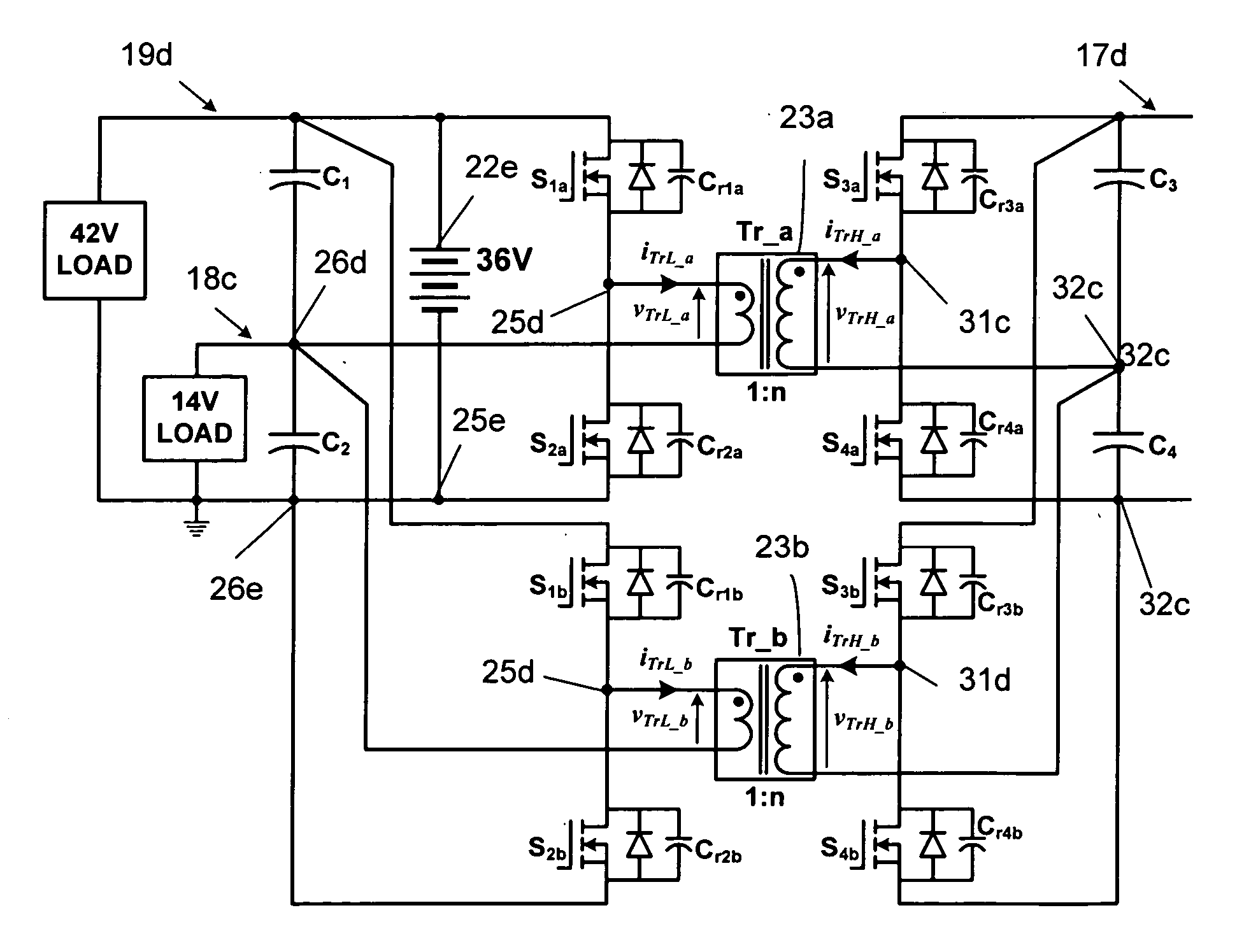
[0031]FIG. 6 shows a third embodiment with a modular structure, where two basic circuit modules of FIG. 3 are connected in parallel while sharing the dc bus capacitors C1, C2, C3 and C4. This provides a convenient way not only to scale up the power levels but also to reduce the ripple currents in the dc bus capacitors. Because a given capacitor can only handle a fixed amount of ripple current, a smaller ripple current requires less capacitance to bear it and thus reduces the capacitor's volume and cost. More modules can be added similarly.

[0032]FIG. 7 illustrates the voltage phase angle shifts for the embodiment in FIG. 6. To reduce the ripple currents to the dc bus capacitors, the switches are gated in the way that the respective low and high voltages across the two transformer terminals, vtrL—hd a and vtrL—b, vtrH—a and vtrH—b, have a phase angle displacement, δ, where the dead time is omitted for simplicity. For the embodiment with two modules in FIG. 6, the preferred value of th...


PUM


Abstract

A circuit and method of providing three dc voltage buses and transforming power between a low voltage dc converter and a high voltage dc converter, by coupling a primary dc power circuit and a secondary dc power circuit through an isolation transformer; providing the gating signals to power semiconductor switches in the primary and secondary circuits to control power flow between the primary and secondary circuits and by controlling a phase shift between the primary voltage and the secondary voltage. The primary dc power circuit and the secondary dc power circuit each further comprising at least two tank capacitances arranged in series as a tank leg, at least two resonant switching devices arranged in series with each other and arranged in parallel with the tank leg, and at least one voltage source arranged in parallel with the tank leg and the resonant switching devices, said resonant switching devices including power semiconductor switches that are operated by gating signals. Additional embodiments having a center-tapped battery on the low voltage side and a plurality of modules on both the low voltage side and the high voltage side are also disclosed for the purpose of reducing ripple current and for reducing the size of the components.

Description

CROSS REFERENCE TO RELATED APPLICATIONS [0001] The benefit of U.S. Provisional Appl. No. 60 / 775,433 filed Feb. 21, 2006, is claimed herein.STATEMENT REGARDING FEDERALLY SPONSORED RESEARCH [0002] This invention was made with Government support under Contract No. DE-AC05-00OR22725 awarded to UT-Battelle, LLC, by the U.S. Department of Energy. The Government has certain rights in this invention.TECHNICAL FIELD [0003] This invention relates to an improvement in dc-to-dc converters for interconnecting multiple electrical networks of different voltages in hybrid electric and electric vehicles, for example. BACKGROUND ART [0004] Because the 14-volt electrical system in present automobiles has reached its limits of capability, a 42-volt power network has been proposed to cope with the increasing electrical loads. This is particularly true for electrical and hybrid vehicles in which more engine-driven mechanical and hydraulic systems are being replaced with electrical systems to increase eff...

Claims


Application Information

Patent Timeline
Patent Type & Authority Applications(United States)
IPC IPC(8): H02M3/335
CPCB60K6/28B60K6/48B60L11/1868H02J1/08H02J2001/008Y02T10/7066H02M3/285H02M3/33584Y02T10/6221Y02T10/7005H02M1/10B60L58/20H02J1/082Y02T10/62Y02T10/70
Inventor SU, GUI-JIA
Owner UT BATTELLE LLC
Why Eureka
Try Eureka