Planar-Resonator Based Optical Chemo- And Biosensor

Inactive Publication Date: 2007-08-23
TEL AVIV UNIV FUTURE TECH DEVMENT
View PDF3 Cites 24 Cited by
  • Summary
  • Abstract
  • Description
  • Claims
  • Application Information

AI Technical Summary

Benefits of technology

[0048] An advantageous feature of the sensors of the present invention is that the energy consumed by the device is provided preferably by optical pumping of the PL material. The energy source may thus be remote from the device. In some embodiments, the sensor output is encoded by the wavelength distribution of the emitted light, and its readout is performed by remote spectral interrogation of this light. A variety of remote readers may be used, including spectrometers, monochromators plus detectors, or properly designed wavelength filters in conjunction with detectors. Because of the robust nature of spectral

Problems solved by technology

A tunable light source is required in order to perform such a measurement, rendering it complex and expensive.
Waveguide grating sensors are not known to be photoluminescent (PL) and therefore do not provide emitted light wavelength shifts for the detection of absorbed molecules.
A major problem with such a structure is that the sensed material has to diffuse into the sensor bulk (volume).
In addition, the emission of light from porous silicon is notoriously inefficient.
A major disadvantage of this scheme of detection is that the tunable filter transmits a different wavelength in each direction.
Th

Method used


Image

  • Planar-Resonator Based Optical Chemo- And Biosensor
  • Planar-Resonator Based Optical Chemo- And Biosensor
  • Planar-Resonator Based Optical Chemo- And Biosensor

Examples


Embodiment Construction

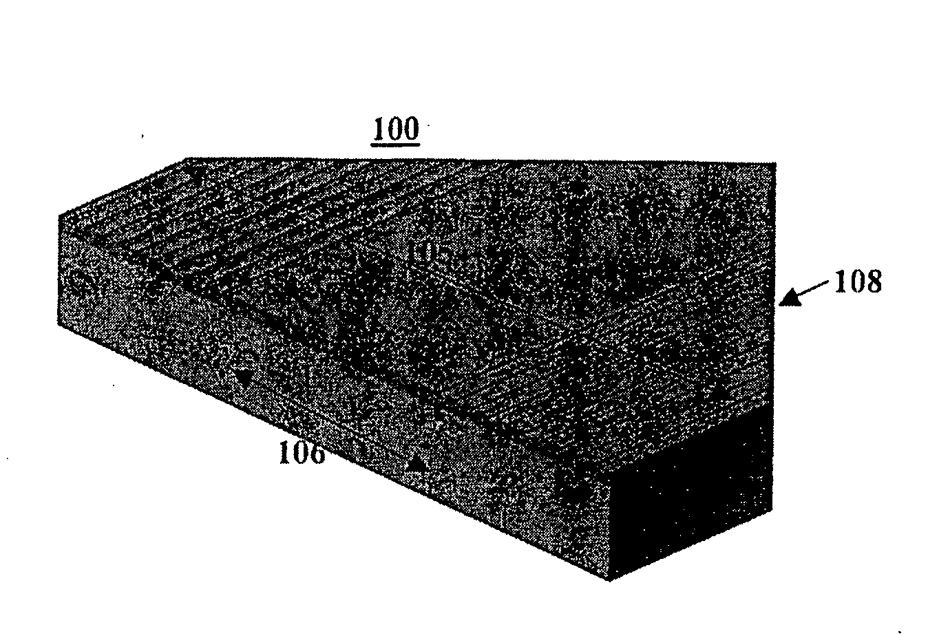
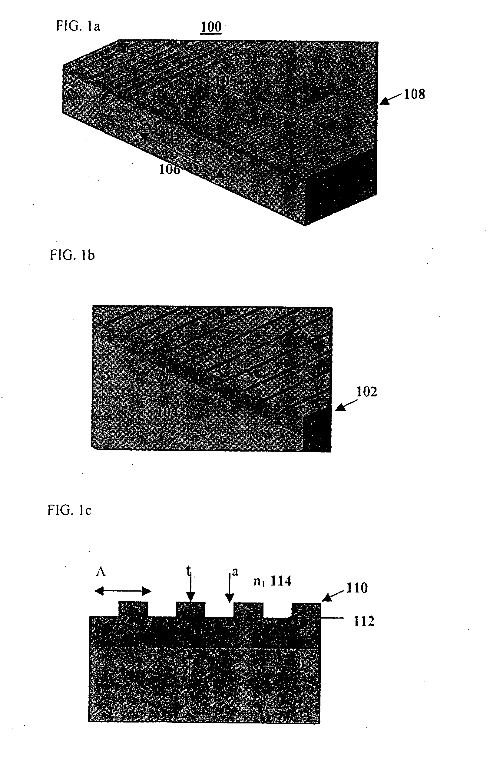
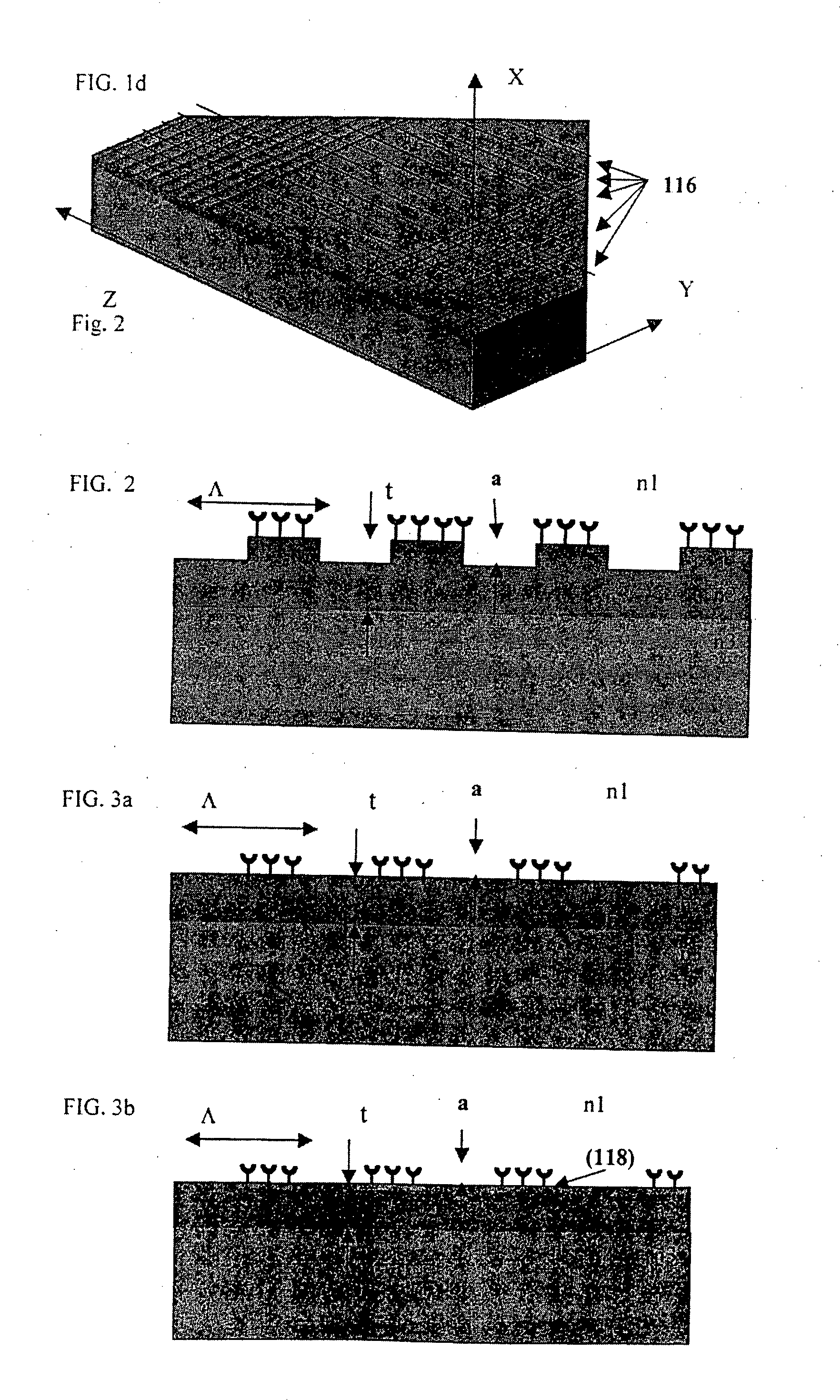
[0062]FIGS. 1a-c show schematically a preferred embodiment of a linear MBRS 100 according to the present invention. The MBRS includes a guiding layer (waveguide) 102 with a refractive index n2 and thickness t formed on a substrate 104 with a smaller refractive index n3. A planar micro-resonant structure 105 formed in waveguide 102 comprises a central section 106 with a length Lin bound by reflection gratings or DBRs 108. The DBRs represent perturbations in the profile of layer 102 and are designed to support reflections of resonant electromagnetic modes, as explained in more detail in the model below. Each DBR has a corrugation structure with parameters defined by a period Λ and a corrugation depth a that defines the distance between corrugation tops 110 and corrugation bottoms 112. The grating structure and the entire waveguide are faced on the side opposite to that of the substrate by a superstrate 114 medium with a refractive index n1.

[0063] Waveguide layer 102 is made preferabl...


PUM


Abstract

A biological or chemical optical sensing device comprises at least one planar micro-resonator structure included in a light emitting waveguide, and at least one biological or chemical probe bound to at least a part of the micro-resonator structure, the probe operative to bind specifically and selectively to a respective target substance, whereby the specific and selective binding results in a parameter change in light emitted from the waveguide. In one embodiment, the micro-resonator is linear. In some embodiments, the sensing device is active, the waveguide including at least one photoluminescent material operative to be remotely pumped by a remote optical source, and the parameter change, which may include a spectral change or a quality-factor change, may be remotely read by an optical reader.

Description

FIELD OF THE INVENTION [0001] The present invention is related to the general field of optical sensors, and in particular to planar miniaturized electro-optical chemo- and biosensors comprising sol-gel photoluminescent resonant structures. BACKGROUND OF THE INVENTION [0002] Optical sensing devices that use effects based on the amplitude, phase, frequency, and state of polarization of electromagnetic radiation are known (see e.g. T. Hirschfeld, J. Callis and B Kowalski, “Chemical sensing in process analysis”, Science, vol. 226 (1984) 312-318]. In chemo- and biosensors, all possible interactions between radiation and matter such as dispersion (refractive index), reflection (diffuse and specular), scattering (Raman), changing transmission, or quenching of fluorescence have been applied to monitor analyte / sensor interactions. Devices based on total internal reflection and evanescent-field effects are also known (see e.g. O. S. Wolfbeis, “Analytical chemistry with optical sensors”, Frese...

Claims


Application Information

Patent Timeline
IPC IPC(8): G02B6/00G01N33/543
CPCG01N21/774G01N21/7746G02B6/124G02B6/12007G01N33/54373
Inventor PELED, ASHERNATHAN, MENACHEMRUSCHIN, SHLOMOZOHAR, TALI
Owner TEL AVIV UNIV FUTURE TECH DEVMENT
Why Eureka
Try Eureka