

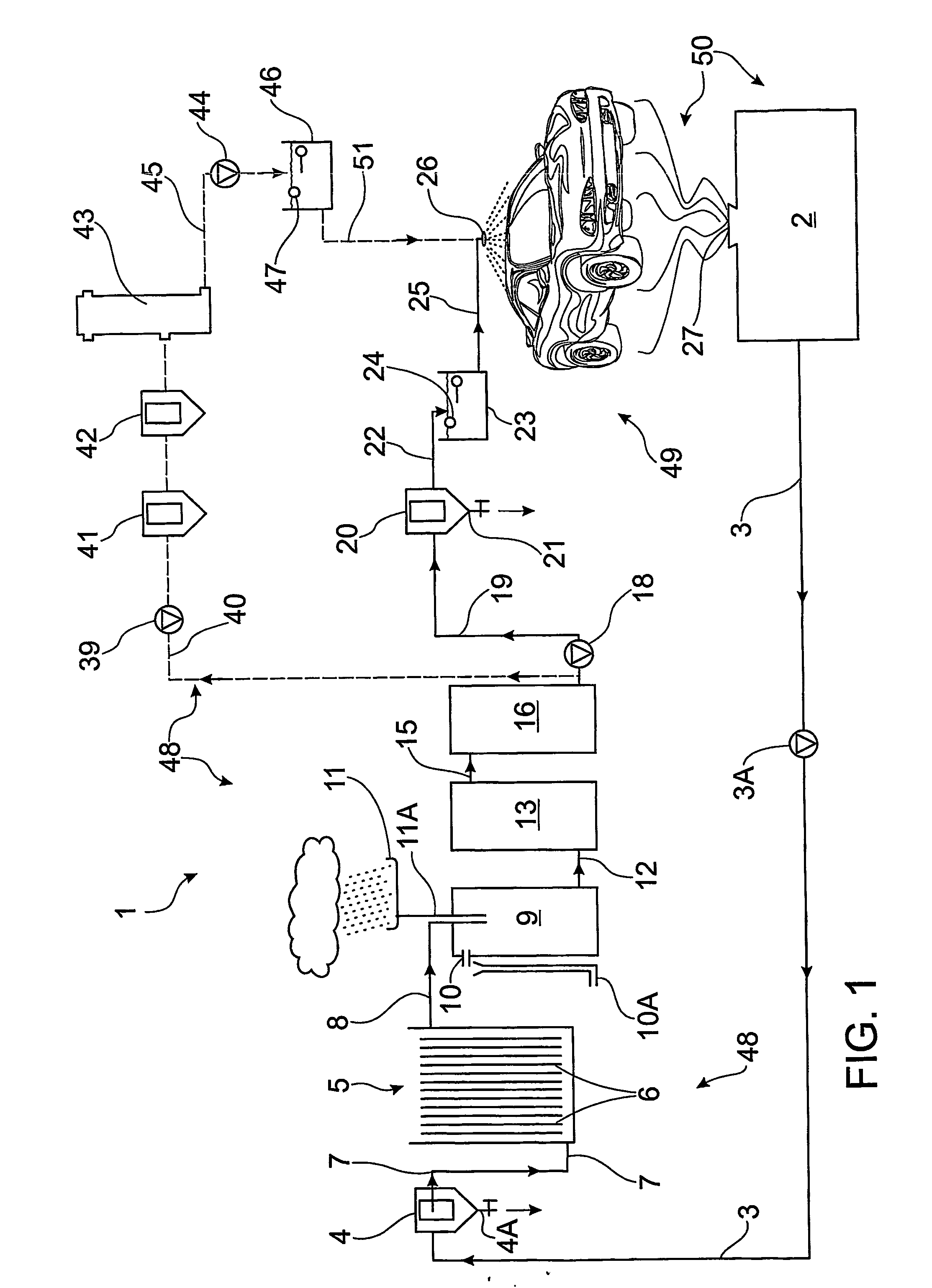
Wastewater Purification Method
a technology of wastewater and purification method, which is applied in the direction of waste water treatment from vehicle washing, water/sludge/sewage treatment, specific water treatment objectives, etc., can solve the problems of large amount of waste water, water would take a long time to pass through the system, and waste of such wastewater
- Summary
- Abstract
- Description
- Claims
- Application Information
AI Technical Summary
Benefits of technology
Problems solved by technology
Method used
Image

Examples
example 1
[0096] he following example applies to an EC system for the removal of shower and washbasin contaminants from a wastewater sample. [0097] Contaminants present in sample—suspended solids (dirt), TP (total phosphorous-detergents) [0098] The sample was grey-coloured water with soap suds and dirt in solution. There were some suspended particles and the sample was stirred sample stirred while treated. [0099] The raw sample had a pH of 5.4 and conductivity 780 μS / cm. [0100] Flow rate: 1 L / min
Experimental Results
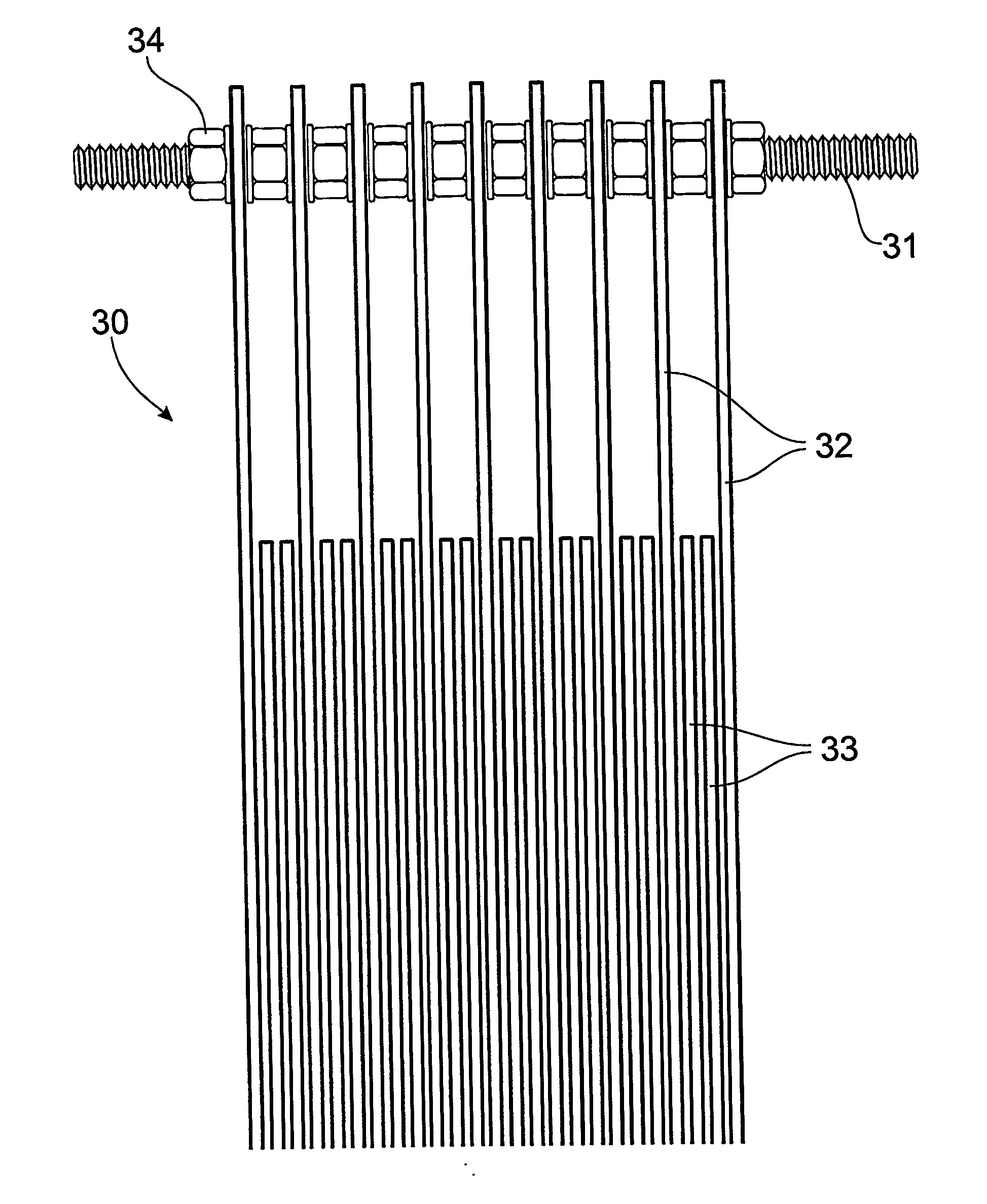
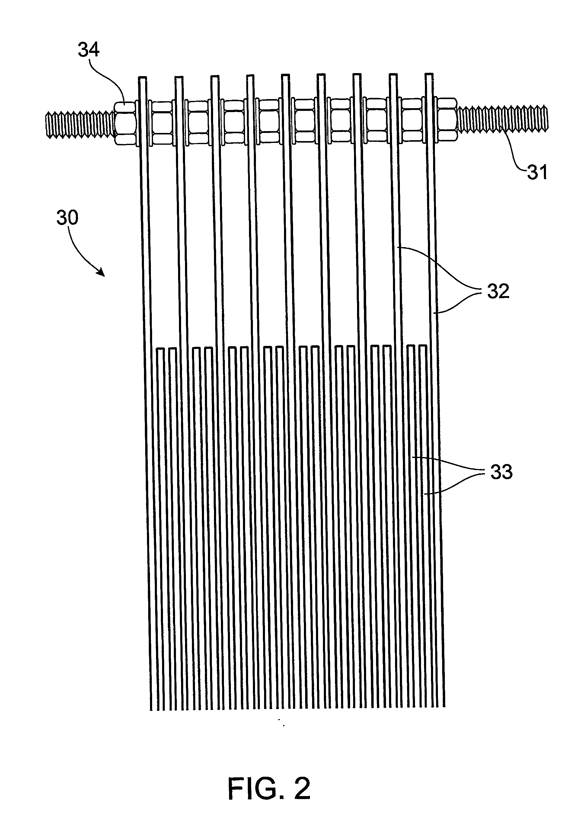
[0101] The most successful treatment was achieved using the following parameters: [0102] Electrode type: Aluminium [0103] Number of electrodes=8 [0104] Number of connections=4 (electrodes 1, 3, 6, 8) [0105] Volts=35 [0106] Amps=4.8 [0107] Coagulant produced—light density foam coagulant and a very clear aqueous layer. [0108] Very effective removal of dirt and detergents was observed. [0109] Water re-cycling is an option for the treatment process. [0110] The sample was treated wit...
example 2
[0111] The following example applies to an EC system for the removal of restaurant discharge contaminants (food and fats) from a wastewater sample. [0112] Contaminants present in sample—suspended solids, total phosphorous (TP—detergents), food, oil and grease (cooking oils), BOD (biological oxygen demand—food proteins), total Kjeldahl Nitrogen (TKN—nutrients). [0113] The sample was grey / brown-coloured water with food particles in solution. [0114] Preferably, the sample is pre-filtered prior to treatment. [0115] The raw sample had a pH of 5.5 and conductivity 1,150 μS / cm. [0116] Flow rate: 1 L / min
Experimental Results [0117] The most successful treatment was achieved using the following parameters: [0118] Electrode type: Aluminium [0119] Number of electrodes=8 [0120] Number of connections=4 (electrodes 1, 3, 6, 8) [0121] Volts=50 [0122] Amp=9.5 [0123] Coagulant produced—high density / large volume foam coagulant due to the high BOD content. Fats and greases were also removed. There wa...
example 3
[0126] The following example applies to an EC system for the removal of engine oil contaminants from a wastewater sample from a car service facility. [0127] Contaminants present in sample—suspended solids, TP (detergents), car oil and grease (engine oils), petrochemicals and dissolved metals. [0128] The sample was a brown / black emulsion, oil / grease emulsion with dirt and detergents in solution. [0129] The raw sample had a pH of 6.8 and conductivity 490 μS / cm. [0130] Flow rate: 1 L / min
Experimental Results [0131] The most successful treatment was achieved using the following parameters: [0132] Electrode type: Aluminium [0133] Number of electrodes=8 [0134] Number of connections=4 (electrodes 1, 3, 6, 8) [0135] Volts=51 [0136] Amps=3.0 [0137] Coagulant produced—high density / low volume coagulant [0138] Oils and greases, dirt and other components were removed. [0139] There was a very clear aqueous layer. Therefore the method was successful [0140] Water re-cycling is an option for the tr...
PUM
| Property | Measurement | Unit |
|---|---|---|
| size | aaaaa | aaaaa |
| voltage | aaaaa | aaaaa |
| voltage | aaaaa | aaaaa |
Abstract
Description
Claims
Application Information