
Flexible substrate

a flexible substrate and substrate technology, applied in the direction of solid-state devices, printed circuit aspects, basic electric elements, etc., can solve the problems of difficulty in using the same wire bonding or soldering as is used with rigid substrates, lack of rigidity and heat resistance, and the tendency of conventional flexible substrates to shrink. deformation

Inactive Publication Date: 2007-08-30
SANYO ELECTRIC CO LTD
View PDF14 Cites 10 Cited by
  • Summary
  • Abstract
  • Description
  • Claims
  • Application Information

AI Technical Summary

Benefits of technology

[0008] The present invention has been made to resolve problems as described above, and a general purpose thereof is to provide a flexible substrate which has not only flexibility but also rigidity and heat resistance.
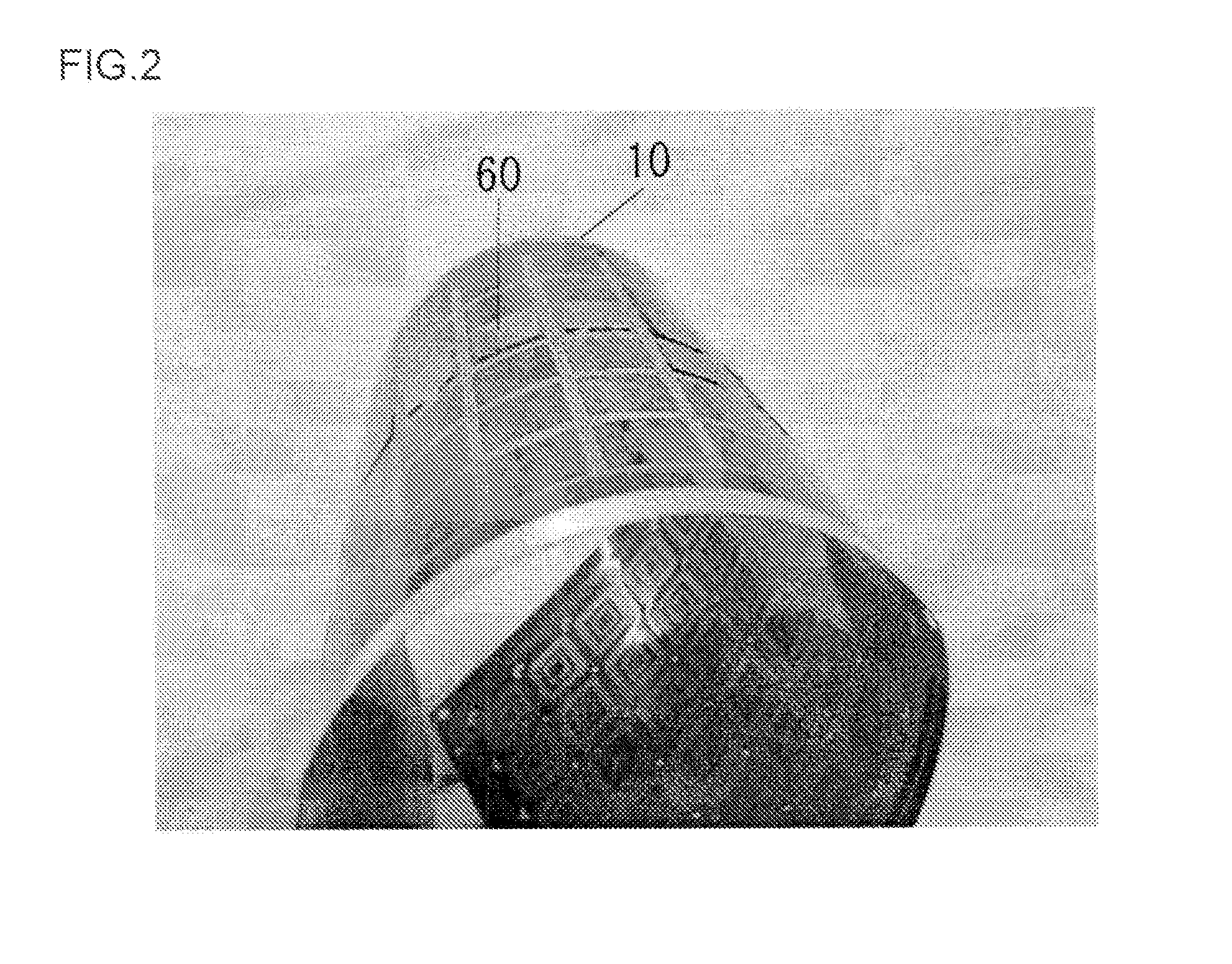
[0010] According to this embodiment, the insulating resin layer itself has a material property of being rigid and hear resistant, and it has flexibility in the form of a substrate and can be freely bent or curved. As a result, such processes as wire bonding and soldering can be used even for a bent part of the a circuit board. Thereby, circuit elements can be mounted on not only a bent portion bur also an unbent portion. Hence, the increased packaging area on the flexible substrate 10 with circuit elements mounted also on the bent areas thereof contributes to higher density and smaller size of circuit devices.
[0011] In the above embodiment, the insulating resin layer may further contain moisture resistance. According to this embodiment, a swelling deformation because of water absorption in the insulating layer is suppressed, so that a desirable bonding property with circuit elements can be retained. As a result, reliability can be enhanced as a circuit element mounting substrate or board.
[0012] In any of the above embodiments, the insulating resin layer may further contain rigidity. According to this embodiment, the flexible substrate can be suitably used as a circuit board where once the flexible substrate is folded or folded in a bent state inside a mobile phone, for example, it will be used in the fixed state.
[0013] Also, in any of the above embodiments, at least part of the glass fibers may be exposed on an end face of the insulating resin layer. This arrangement according to this embodiment provides sufficient strength to peripheral edge parts of the insulating resin layer for mounting circuit elements thereon. Thus, by effectively using the peripheral edge area of a circuit board as circuit element mounting area, the packaging area for circuit elements can be increased. Furthermore, when the circuit elements are mounted on the flexible substrate, heat generated by the circuit elements can be easily radiated from the glass fibers exposed on the end faces of the insulating resin layer, so that the heat radiation from the flexible substrate with the circuit elements mounted thereon improves.

Problems solved by technology

The materials used for conventional flexible substrates have mostly been insulating resins like polyimide resins, which generally lack in rigidity and heat resistance.
Thus, they present the problem of difficulty in using the same wire bonding or soldering as is used with rigid substrates.
Also, conventional flexible substrates have been liable to swelling deformation because of their poor heat resistance and moisture resistance, which renders them totally unsuited to multilayered structuring.
On the other hand, the conventional rigid substrates have their problem in that they cannot be deformed like flexible substrates which can be used in the movable parts of mobile equipment.

Method used


Image

  • Flexible substrate
  • Flexible substrate
  • Flexible substrate

Examples


Embodiment Construction

[0024] The invention will now be described by reference to the preferred embodiments. This does not intend to limit the scope of the present invention, but to exemplify the invention.

The present embodiments will now be described with reference to drawings.

[0025] Hereinbelow, the embodiments will be described with reference to the accompanying drawings.

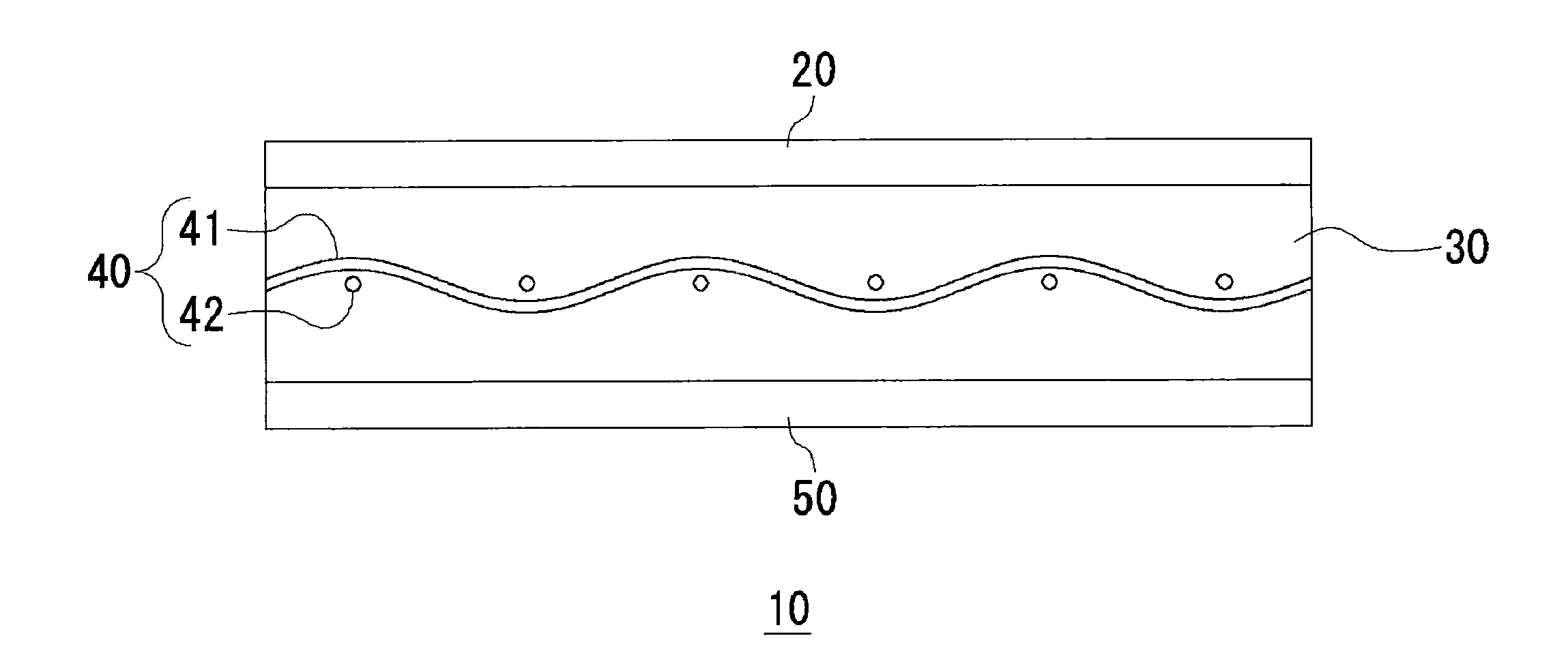
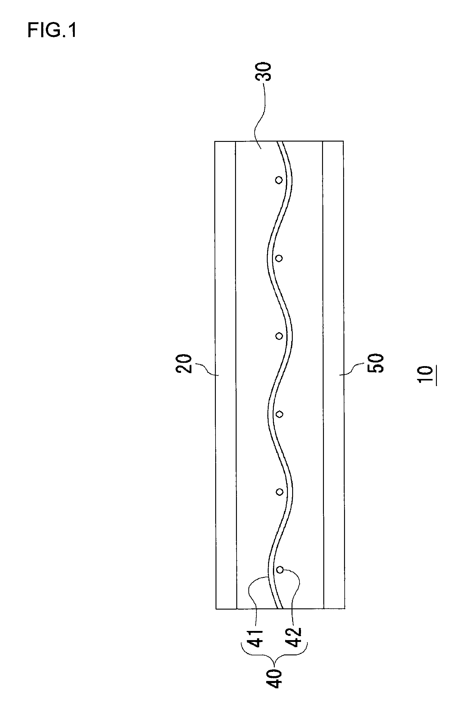
[0026]FIG. 1 is a sectional view showing a structure of a flexible substrate 10 according to an embodiment of the present invention. The flexible substrate 10 includes a first wiring layer 20, an insulating resin layer 30, a glass cloth 40, and a second wiring layer 50.

[0027] The first wiring layer 20 and the second wiring layer 50, which are made of a metal such as copper, have their respective wiring patterns. The first wiring layer 20 and the second wiring layer 50 may be produced, for instance, by first pressure-bonding copper foil on the insulating resin layer 30, then forming a resist according to a desired wiring pattern on...


PUM

PropertyMeasurementUnit
Thicknessaaaaaaaaaa
Electrical resistanceaaaaaaaaaa
Flexibilityaaaaaaaaaa

Abstract

A flexible substrate is provided which contains not only flexibility but also rigidity and hear resistance. A flexible substrate includes a first wiring layer, an insulating resin layer, a glass cloth and a second wiring layer. The insulating layer is formed by an insulating material, such as a BT resin, epoxy resin or the like that contains a high elastic modulus, heat resistance and moisture resistance. The film thickness of the insulating resin layer is thinned down to about 60 μm. As a reinforcing material, the glass cloth is embedded in the insulating resin layer. With this structure, the flexible substrate attains flexibility and at the same time in any of the first wiring layer and the second wiring layer, circuit elements can be mounted both on a curved area and a non-curved area of the wiring layers.

Description

BACKGROUND OF THE INVENTION [0001] 1. Field of the Invention [0002] The present invention relates to a flexible substrate known also as a flexible wiring board and, more particularly, to a flexible substrate suited to the mounting of circuit elements thereon. [0003] 2. Description of the Related Art [0004] In recent years, as more and more electronic equipment come in smaller sizes and with higher functions, the on-going trend in the circuit devices used in such electronic equipment is toward smaller size, higher density, and greater sophistication such as multiple functions. Also, demand is growing for wiring boards having flexibility, called flexible substrates, so as to wire a large number of circuit devices within a housing of electronic equipment. Use of such flexible substrates increases the freedom of arrangement of circuit devices, thus making it possible to place more circuit devices in a limited space of housing. [0005] So far, because of their flexibility, flexible substr...

Claims


Application Information

Patent Timeline
IPC IPC(8): H01L23/053
CPCH01L23/4985H05K1/0366H05K1/0393H05K2201/029H01L2924/0002H01L2924/00
Inventor MURAI, MAKOTOUSUI, RYOSUKE
Owner SANYO ELECTRIC CO LTD
Learn More