Optical transmission device and light-receiving module
a technology of optical transmission device and light-receiving module, which is applied in the direction of optical waveguide light guide, instruments, optical elements, etc., can solve the problems of difficult coupling as compared with the conventional general waveguide, and achieve the effect of convenient fabrication
- Summary
- Abstract
- Description
- Claims
- Application Information
AI Technical Summary
Benefits of technology
Problems solved by technology
Method used
Image
Examples
first embodiment
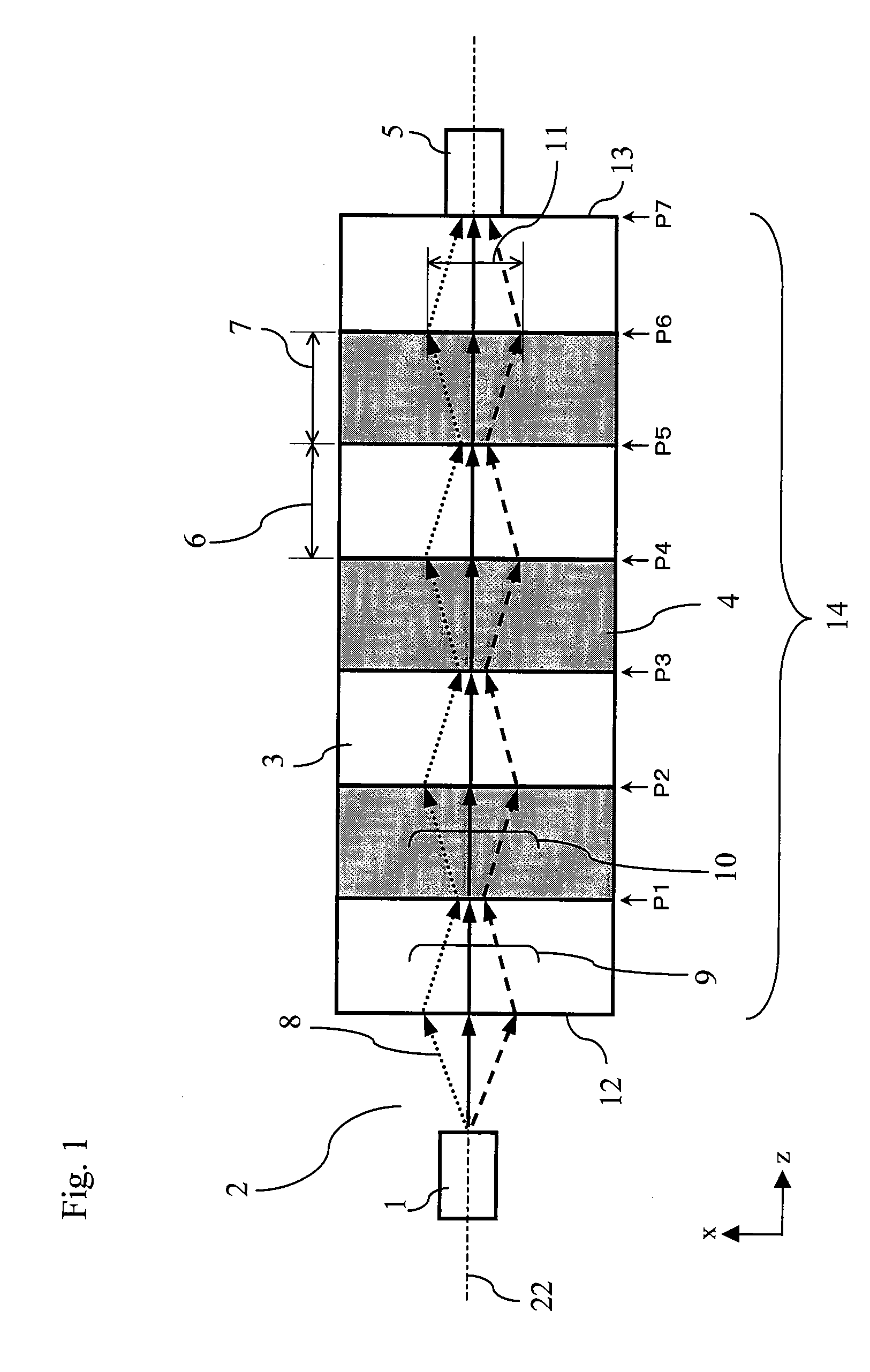
[0111]FIG. 1 illustrates a schematic configuration diagram of a light-receiving module according to a first embodiment of the present invention.
[0112] The configuration and operation of the light-receiving module of the first embodiment are described hereinbelow by primarily referring to FIG. 1.
[0113] The light-receiving module of the first embodiment is provided with a transmission section 14 and a light-receiving section 5.
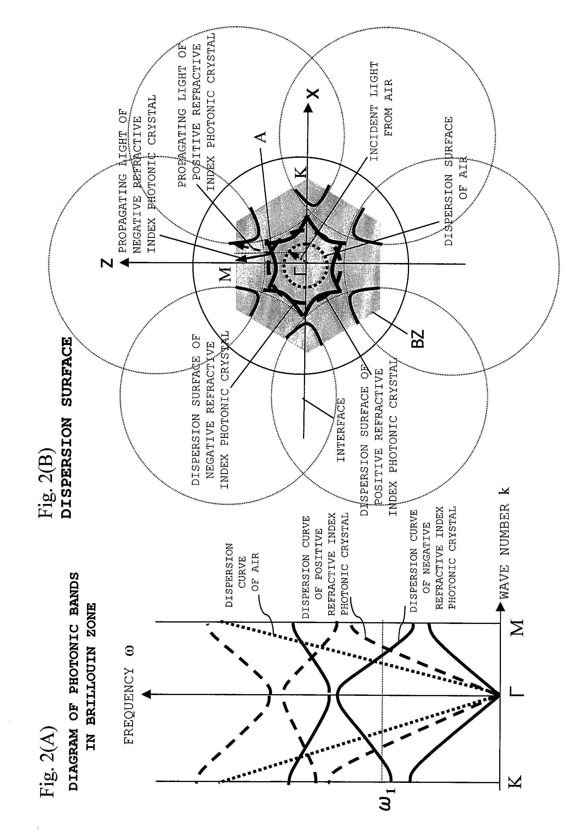
[0114] The transmission section 14 is provided with a plurality of negative refractive index photonic crystals 3 having a negative refraction angle with respect to an incident angle of an incident light 8 from a light source 1 isolated by a free space 2 and a plurality of positive refractive index photonic crystals 4 having a positive refraction angle with respect to the incident angle. The negative and positive refractive index photonic crystals 3 and 4 are arranged in tandem alternatively on an optical axis 22 of the transmission section 14 so that the nega...
second embodiment
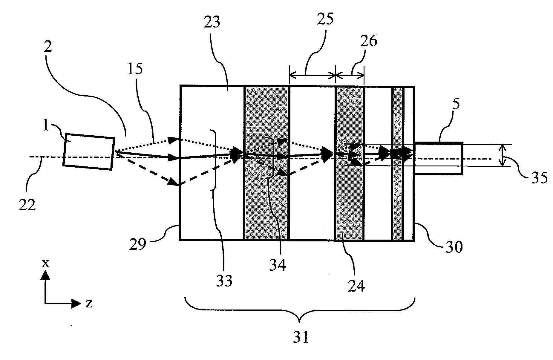
[0139]FIGS. 3 and 4 illustrate schematic configuration diagrams of the light-receiving module according to a second embodiment of the present invention. FIG. 3 illustrates the case where the incident light is not angularly misaligned, and FIG. 4 illustrates the case where the incident light enters while being angularly misaligned. In the respective drawings, like reference numerals denote like components as those in FIG. 1.
[0140] The configuration and operation of the light-receiving module of the second embodiment are described hereinbelow by primarily referring to FIGS. 3 and 4.
[0141] As compared to the light-receiving module of the first embodiment where the negative and positive refractive index photonic crystals 3 and 4 having the same optical path length are arranged in tandem alternatively, the light-receiving module of the second embodiment is different in that negative refractive index photonic crystals 23 and positive refractive index photonic crystals 24 with varying th...
third embodiment
[0154]FIG. 5 illustrates a schematic configuration diagram of the light-receiving module according to a third embodiment of the present invention. Like reference numerals denote like components as those in FIG. 1.
[0155] The configuration and operation of the light-receiving module of the third embodiment are described hereinbelow by primarily referring to FIG. 5.
[0156] The light-receiving module of the third embodiment is provided with a transmission section 49 and the light-receiving section 5.
[0157] The transmission section 49 is provided with a plurality of graded negative refractive index photonic crystals 17 having the negative refraction angle and a plurality of graded positive refractive index photonic crystals 18 having the positive refraction angle, which are arranged in tandem alternatively on the optical axis 22 of the transmission section 49 so that the graded negative refractive index photonic crystals 17 are disposed at both an incident end 47 and an outgoing end 48...
PUM
 Abstract
Description
Claims
Application Information
 - R&D
- Intellectual Property
- Life Sciences
- Materials
- Tech Scout
- Unparalleled Data Quality
- Higher Quality Content
- 60% Fewer Hallucinations
Browse by: Latest US Patents, China's latest patents, Technical Efficacy Thesaurus, Application Domain, Technology Topic, Popular Technical Reports.
© 2025 PatSnap. All rights reserved.Legal|Privacy policy|Modern Slavery Act Transparency Statement|Sitemap|About US| Contact US: help@patsnap.com


