Multiple stage separator vessel

Active Publication Date: 2007-08-30
UOP LLC
View PDF4 Cites 14 Cited by
  • Summary
  • Abstract
  • Description
  • Claims
  • Application Information

AI Technical Summary

Benefits of technology

[0012] In an embodiment, a separation vessel and process are provided that advantageous

Problems solved by technology

For every ton of cracked product made, approximately 5 tons of catalyst are needed, hence the considerable circulation requirements.
Coupled with this need for a large inventory and recycle of catalyst with small particle diameters is the ongoing challenge to prevent this catalyst from exiting the reactor/regenerator system into effluent streams.
Additionally, catalyst particles are abrasive and thus are capable of damaging and eroding components located downstream of the regenerator, such as a turbine.
If exposed to catalyst particles, blades of the turbine would erode and result in loss of power recovery efficiency.
Blade accumulation can cause blade tip erosio

Method used


Image

  • Multiple stage separator vessel
  • Multiple stage separator vessel

Examples


example

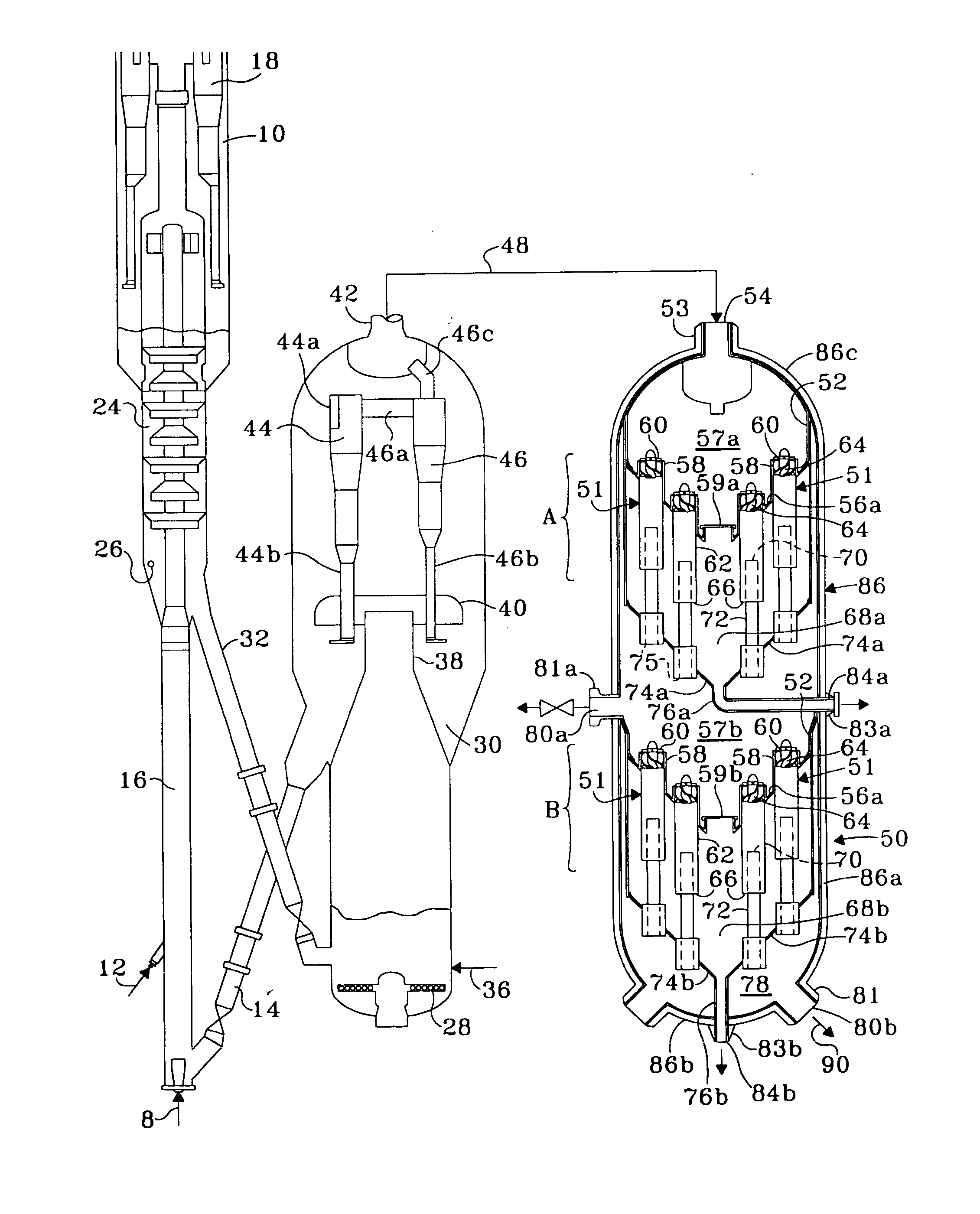
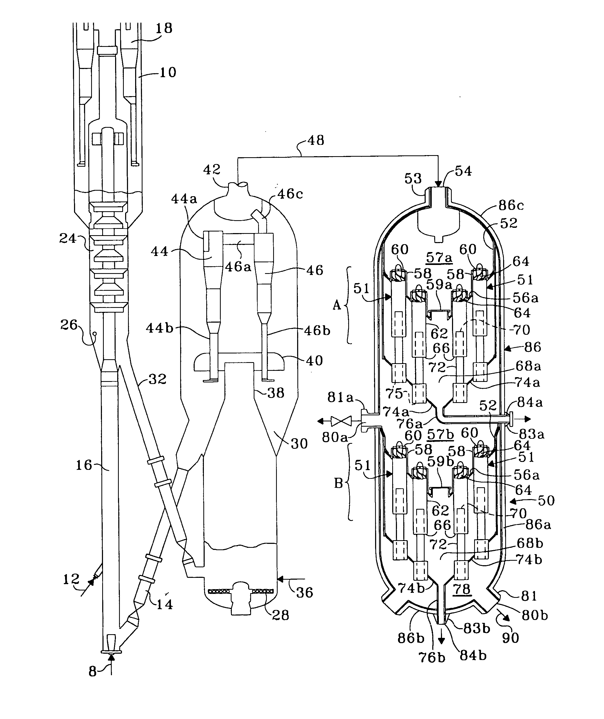
[0029] The projected performance of the MSS in an FCC application has been compared to the performance of a TSS. With a conventional single-stage TSS, wherein the inlet flow into the TSS was 68 lbs / hr of particulate, the single stage separator yielded a purified gas with an emission of 0.78 lb / 1000 lbs coke. Certain applications may require guaranteed emissions of less than 0.80 lb / 1000 lbs coke, in which case such a single-stage separator would not provide a desired design margin of performance. We projected, based on data from operating units, that if all of the purified gas from a conventional TSS with a single stage at a loading of 14 lbs / hr of particulate were introduced to a second stage as would occur in an MSS vessel of the present invention, it would yield an overall emission of 0.54 lb / 1000 lbs coke, a significant improvement in particulate removal and well within a design margin to satisfy, for example, a guaranteed emission of less than 0.80 lb / 1000 lb coke. This project...


PUM

PropertyMeasurementUnit
Volumetric flow rateaaaaaaaaaa

Abstract

A novel multiple stage separator (MSS) vessel is disclosed wherein the vessel includes at least first and second stages or decks of separation cyclones, the stages arranged for operation in series. Each stage or deck includes an upper and lower tube sheet on which a plurality of cyclones are installed, solid particles in the gas stream being separated from the stream and dispensed between the tube sheets as the stream passes through each stage. The vessel has an inlet to receive a gas stream containing the particulates, and the flow travels typically downwardly, first passing through the first stage, then passing through at least a second stage. When implemented downstream of a fluid catalytic cracking (FCC) unit, the MSS has been found to remove a surprisingly increased amount of particulates over a conventional third stage separator (TSS), which contains a single stage separator.

Description

FIELD OF THE INVENTION [0001] The present invention generally relates to a separator vessel that removes particles from a gas stream laden with solids and more particularly relates to a device commonly known as third stage separator (TSS) vessel for removing catalyst fines from hot regenerator flue gas of a fluid catalytic cracking (FCC) unit. BACKGROUND OF THE INVENTION [0002] FCC technology has long been a predominant means of producing gasoline. In an FCC process, gasoline is formed as the result of cracking heavier (i.e. higher molecular weight), less valuable hydrocarbon feed stocks such as gas oil. Although FCC is a large and complex process involving many factors, a general outline of the technology is presented here in the context of its relation to the present invention. [0003] The FCC process generally includes a reactor that is closely coupled with a regenerator, followed by downstream hydrocarbon product separation. Hydrocarbon feed 15 contacts catalyst in the reactor to...

Claims


Application Information

Patent Timeline
IPC IPC(8): B01D53/00
CPCC10G11/18B04C3/04B01J8/0055
Inventor WALKER, PATRICK D.MYERS, DANIEL N.SEXTON, JEFFREY A.HILL, JOHN F. JR.
Owner UOP LLC
Why Eureka
Try Eureka