Control method for cooling a launch clutch and an electric motor in a hybrid electric vehicle powertrain

Inactive Publication Date: 2007-08-30
FORD GLOBAL TECH LLC
View PDF11 Cites 51 Cited by
  • Summary
  • Abstract
  • Description
  • Claims
  • Application Information

AI Technical Summary

Benefits of technology

[0010] To maximize overall transmission efficiency, the cooling fluid flow rate is made variable and is controlled electronically using a closed loop, digital, microprocessor-based control system.
[0011] An embodiment of the present invention comprises a vehicle launch clutch disposed within the rotor of a high voltage electric motor. Lubrication fluid flow for the launch clutch is distributed to the rotor and the stator of the motor, such that the same fluid flows through both the clutch and the motor. A thermistor is located within the

Problems solved by technology

Continued circulation of cooling fluid through the clutch assembly at this time is a waste of energy, which reduces the overall efficiency of the transmission.
To ensure robustness, the open loop cont

Method used


Image

  • Control method for cooling a launch clutch and an electric motor in a hybrid electric vehicle powertrain
  • Control method for cooling a launch clutch and an electric motor in a hybrid electric vehicle powertrain
  • Control method for cooling a launch clutch and an electric motor in a hybrid electric vehicle powertrain

Examples


Embodiment Construction

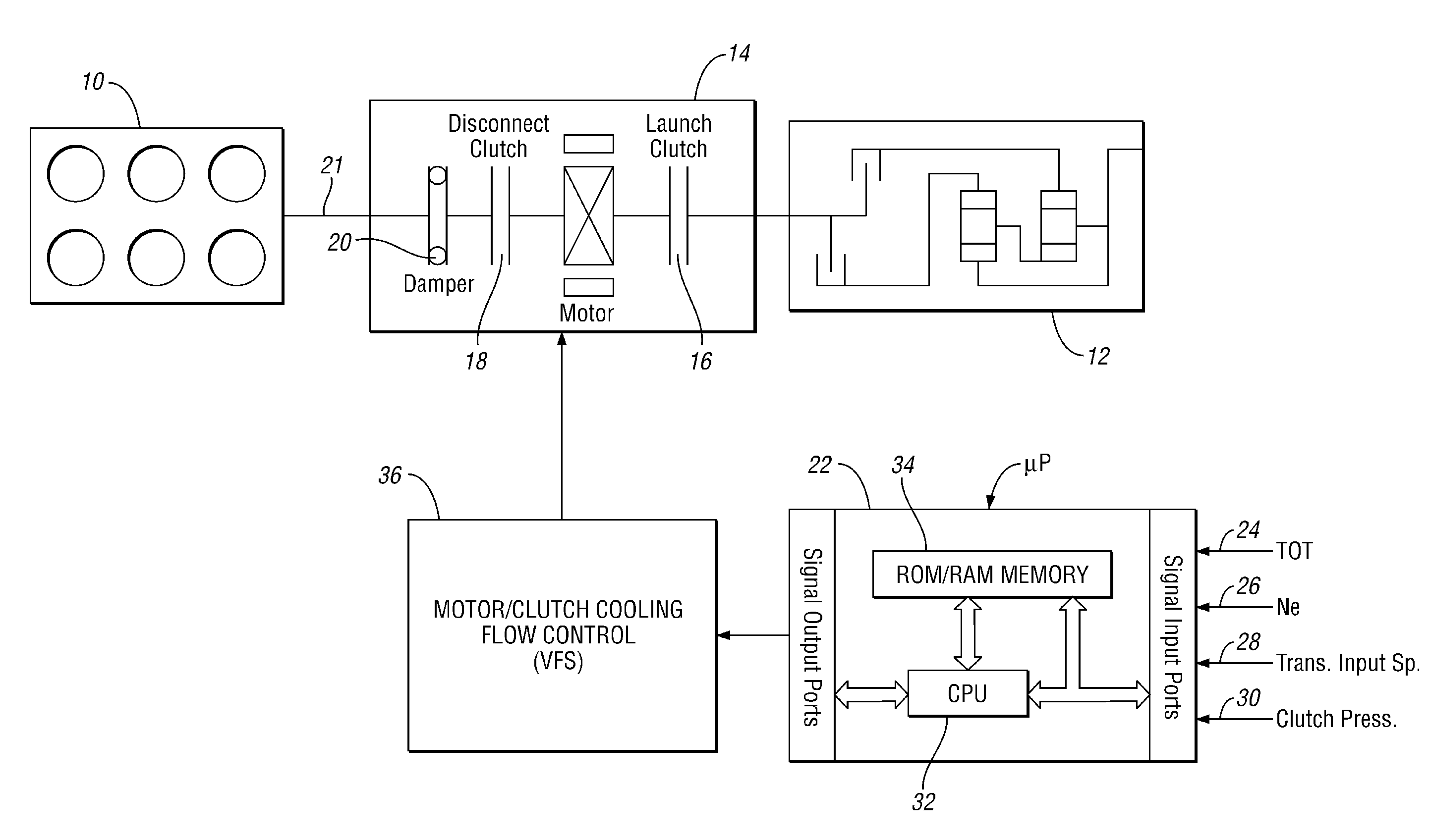
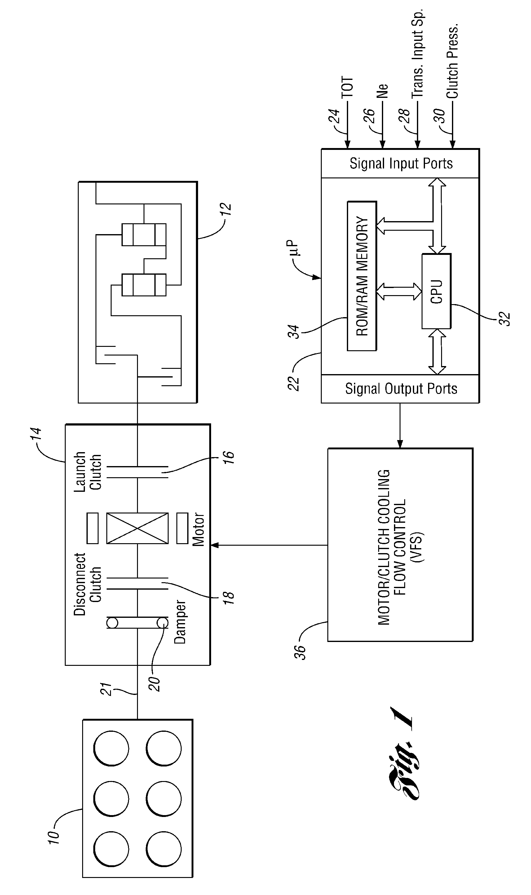
[0021] In the schematic drawing of the powertrain of FIG. 1, an internal combustion engine is shown at 10 and a multiple ratio transmission is shown at 12. An electric motor, a disconnect clutch and a launch clutch form a part of a motor and clutch assembly 14. Assembly 14 is disposed in series relationship with respect to the transmission 12 as engine torque is delivered to vehicle traction wheels at the torque output side of the transmission 12.

[0022] The launch clutch for the assembly 14 of FIG. 1 is designated by reference numeral 16. A disconnect clutch for the assembly 14 is designated by reference numeral 18. A damper assembly, schematically shown at 20, is situated between an engine power output shaft 21 and the disconnect clutch 18.

[0023] A microprocessor 22, which will be described with reference to FIGS. 3 and 4, receives signals representing powertrain operating variables, which include transmission oil temperature 24, engine speed 26 and transmission input speed 28. I...


PUM


Abstract

A method is disclosed for controlling a rate of flow of cooling oil to a friction launch clutch and electric motor in a hybrid electric vehicle powertrain. The rate of flow is determined by changes in clutch temperature and motor temperature. Cooling oil flow in excess of the flow required to maintain a desired temperature is avoided.

Description

BACKGROUND OF THE INVENTION [0001] 1. Field of the Invention [0002] The invention relates to friction clutches for establishing and disestablishing torque flow paths in a hybrid electric vehicle powertrain. [0003] 2. Background Art [0004] A hybrid electric vehicle powertrain with an internal combustion engine and a high voltage electric motor arranged in series is disclosed in U.S. Pat. No. 6,585,066. A powertrain of that type sometimes is referred to as a modular hybrid transmission when an electric motor portion of the powertrain and a discrete ratio transmission mechanism comprise separate modules that are integrated in a compact assembly capable of delivering driving torque through both an electromechanical torque flow path and a fully mechanical torque flow path. The torque capacity of one path supplements the torque capacity of the other. A fully electric driving torque flow path may be obtained using the motor solely. [0005] In the powertrain disclosed in U.S. Pat. No. 6,585,...

Claims


Application Information

Patent Timeline
IPC IPC(8): B60W10/02
CPCB60K6/387Y10T477/26B60K6/48B60K6/547B60K2001/003B60L2240/421B60W10/02B60W20/00B60W2510/0241B60W2510/081F16D25/123Y02T10/6221Y02T10/642B60W10/08B60K2001/006B60W2510/087Y10T477/653Y10T477/70Y10T477/27B60K6/405Y02T10/62Y02T10/64B60W20/40
Inventor ORTMANN, WALTERKRASKA, MARVIN
Owner FORD GLOBAL TECH LLC
Why Eureka
Try Eureka