Microtiter plate, method of manufacturing thereof and kit

a microtiter plate and microtiter plate technology, applied in the field of biological sample processing, can solve the problems of not being able to transfer the same types of features and materials to the higher well density used, and not being able to meet the stresses and thermal performance needs of high temperature cycling applications. achieve novel thermally stable and robust, and increase the throughput of multiple samples high temperature thermal cycling processes

Inactive Publication Date: 2007-09-13
FINNZYMES INSTR
View PDF21 Cites 31 Cited by
  • Summary
  • Abstract
  • Description
  • Claims
  • Application Information

AI Technical Summary

Benefits of technology

[0014] It is an aim of the invention to provide a microtiter plate, which enables increasing the throughput of multiple-sample high temperature thermal cycling processes. In particular, it is an aim of the invention to provide a novel thermally stable and robust construction especially for use for microtiter plates having a well-to-well pitch as small as 2.25 mm, and even less, and a wall thickness of less than about 0.0065 inch (less than about 0.17 mm).

Problems solved by technology

To date there has been little progress made in designing manufacturing and selling microtiter plates of densities below a 4.5 mm pitch for thermal cycling purposes.
Although such plates are optimal for performing biological reactions at or near room temperature, they are not designed to handle the stresses and thermal performance needs of high temperature cycling applications such as PCR.
To date, however, these same types of features and materials have been unable to be transferred to the higher well density used, for example, in 1536-well plates for thermal cycling applications.
A major drawback of such a plate is that it has to be manufactured in several steps and the parts need to be attached together before use.
Moreover, the rigidity of the upper portion, and consequently the whole plate is low due to the structural non-integrity.

Method used


Image

  • Microtiter plate, method of manufacturing thereof and kit
  • Microtiter plate, method of manufacturing thereof and kit
  • Microtiter plate, method of manufacturing thereof and kit

Examples


Embodiment Construction

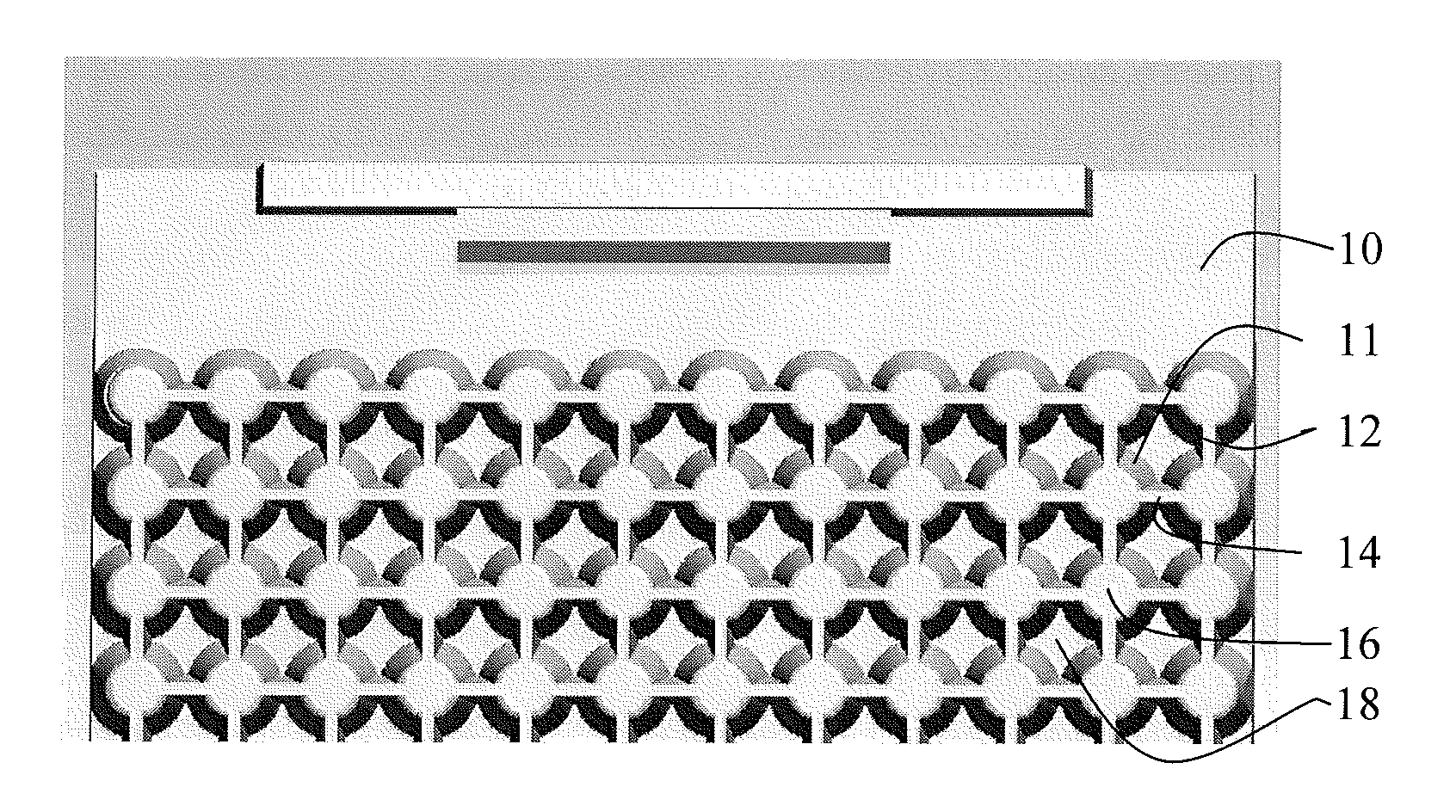
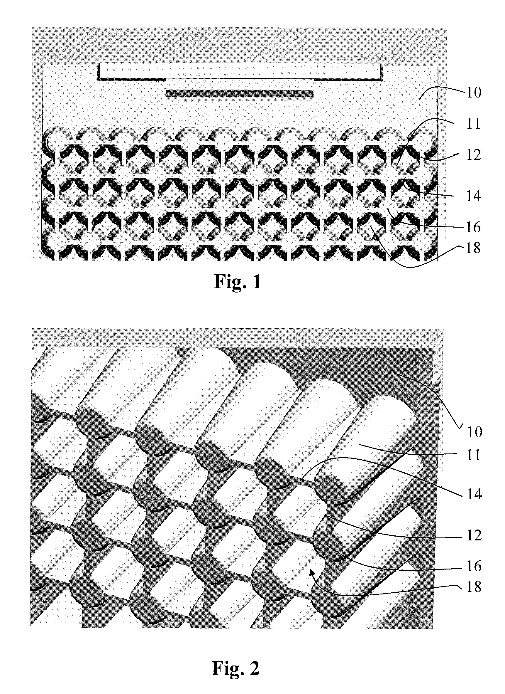
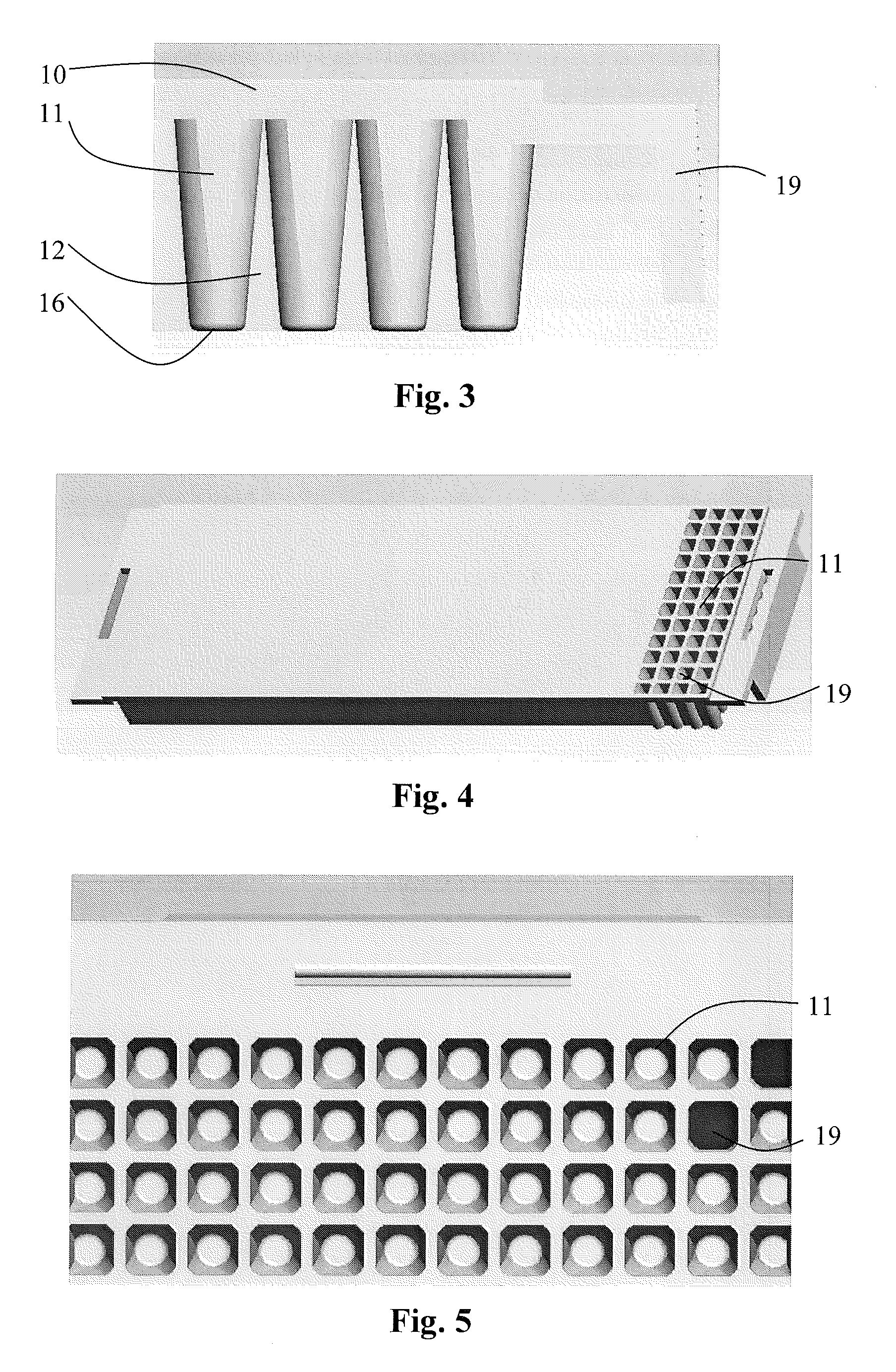
[0054] FIGS. 1 to 5 show one embodiment of a microtiter plate having round conical wells 11. The deck of the plate is denoted with a reference numeral 10. The wells 11 protrude in a parallel manner from the deck 10 such that their upper (open) ends abut on the upper surface of the deck 10. There are two set of ribs present: the first ribs 14 are arranged to connect the wells in first direction (in the direction of well rows) and the second ribs 12 are arranged to connect the wells in a second direction (in the direction of well columns). In this example, the ribs protrude all the way from the bottom of the deck to the level of the bottoms 16 (closed ends) of the wells, and connect to each other at the bottoms 16 of the wells. An interstitial space 18 bordering on the bottom of the deck and four wells and four respective ribs is formed in the middle of each neighboring four wells set. As the wells 11 have the shape of a truncated cone and the ribs are connected from their sides to th...


PUM

PropertyMeasurementUnit
thicknessaaaaaaaaaa
thicknessaaaaaaaaaa
volumesaaaaaaaaaa

Abstract

The invention relates to a vessel and kit for thermal cycling applications, a method for manufacturing such a vessel. The vessel comprises, in the form of a planar grid having a predefined pitch, a plurality of sample wells each having a well wall, which defines an open well end and a closed well end. According to the invention there are provided a plurality of ribs between pairs of adjacent wells, the ribs being connected to the walls of the wells and extending essentially in a plane perpendicular to the plane of the well grid. The invention enables manufacturing of dense microtiter plates, which are stable enough to be used in high temperature applications and allow for more efficient manufacturing of the plate.

Description

BACKGROUND OF THE INVENTION [0001] 1. Field of the Invention [0002] This application claims benefit of priority under 35 U.S.C. 119(e) to U.S. Provisional Application No. 60 / 758,775, filed Jan. 13, 2006, the entirety of which is incorporated herein by reference. [0003] The invention relates to processing of biological samples. In particular, the invention concerns microtiter plates, which are commonly used for performing Polymerase Chain Reaction (PCR) Processes. Such plates have a plurality of wells arranged in a grid, each of the wells being capable of holding a small amount of biological sample. The invention concerns also a method of manufacturing such plates, use of such a method and a kit including such plates. [0004] 2. Description of Related Art [0005] Biological samples are processed in industrial and clinical diagnostics, pharmaceutical and research applications, and as processes have improved, the need for increasing the number and speed of samples processed has also incr...

Claims


Application Information

Patent Timeline
Patent Type & Authority Applications(United States)
IPC IPC(8): C12M1/34B01L3/00
CPCB01L3/50851B01L2200/12B29C45/561B01L2300/0858B29C45/2624B01L2300/0829
Inventor COHEN, DAVID A.MORTILLARO, MICHAEL J.TURNER, BRUCE R.
Owner FINNZYMES INSTR
Why Eureka
Try Eureka