Rotor defining a fluid separation chamber of varying volume

a fluid separation chamber and rotating technology, applied in the direction of centrifuges, rotary centrifuges, etc., can solve the problems of large continuous systems, large diameter, complicated setup and use, and use of two separate channels at the same time to drive blood, so as to increase reduce the capacity of the processing chamber, increase the effect of the processing chamber

Inactive Publication Date: 2007-09-13
CHAMMAS JACQUES
View PDF56 Cites 40 Cited by
  • Summary
  • Abstract
  • Description
  • Claims
  • Application Information

AI Technical Summary

Problems solved by technology

The disadvantage with this system is that although the processing chamber where the blood is separated has a small volume, it has a relatively large diameter and more often it has a large tube rotating around it at a larger radius.
Consequently, the continuous systems are large and are complicated to set up and use.
A major disadvantage to most continuous systems is that two separate channels are used simultaneously to drive blood from the donor and to return unwanted components back to the donor.
These devices are not used for blood washing and salvaging in the operating room (OR) environment, due to the large size and noise level.
Large rotors speed up the process but require large extracorporeal volume.
Small rotors slow down the process and require many batch cycles to collect one unit of needed component.
The fine thickness of the membrane and the inconsistency in stretching geometry mixed with the induced stresses generated by the centrifugal forces can cause the diaphragm to rupture catastrophically spilling out all the blood.
But the shape and the big size of the rotor necessitate the system to be large and awkward to handle.

Method used


Image

  • Rotor defining a fluid separation chamber of varying volume
  • Rotor defining a fluid separation chamber of varying volume
  • Rotor defining a fluid separation chamber of varying volume

Examples


Embodiment Construction

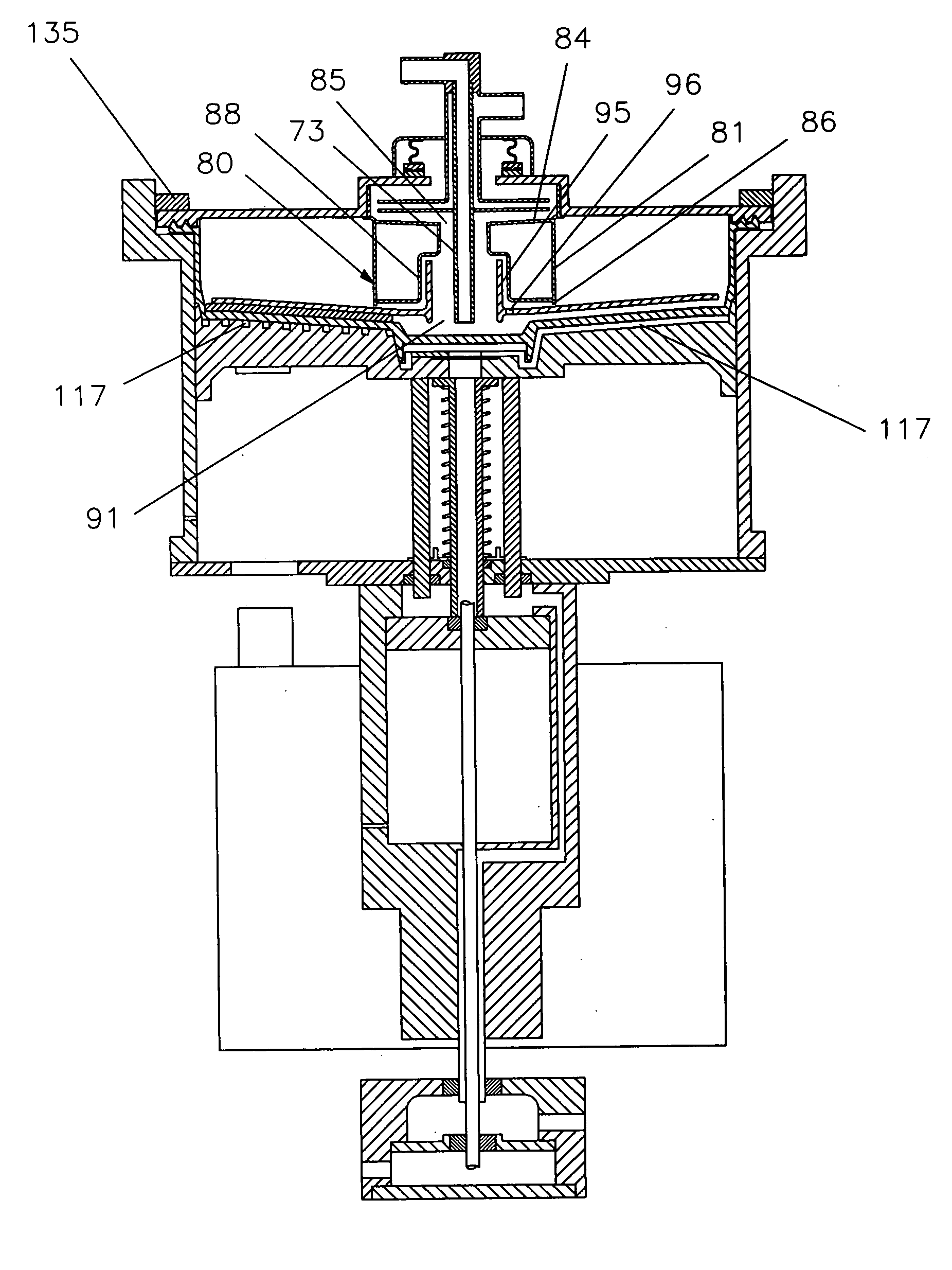
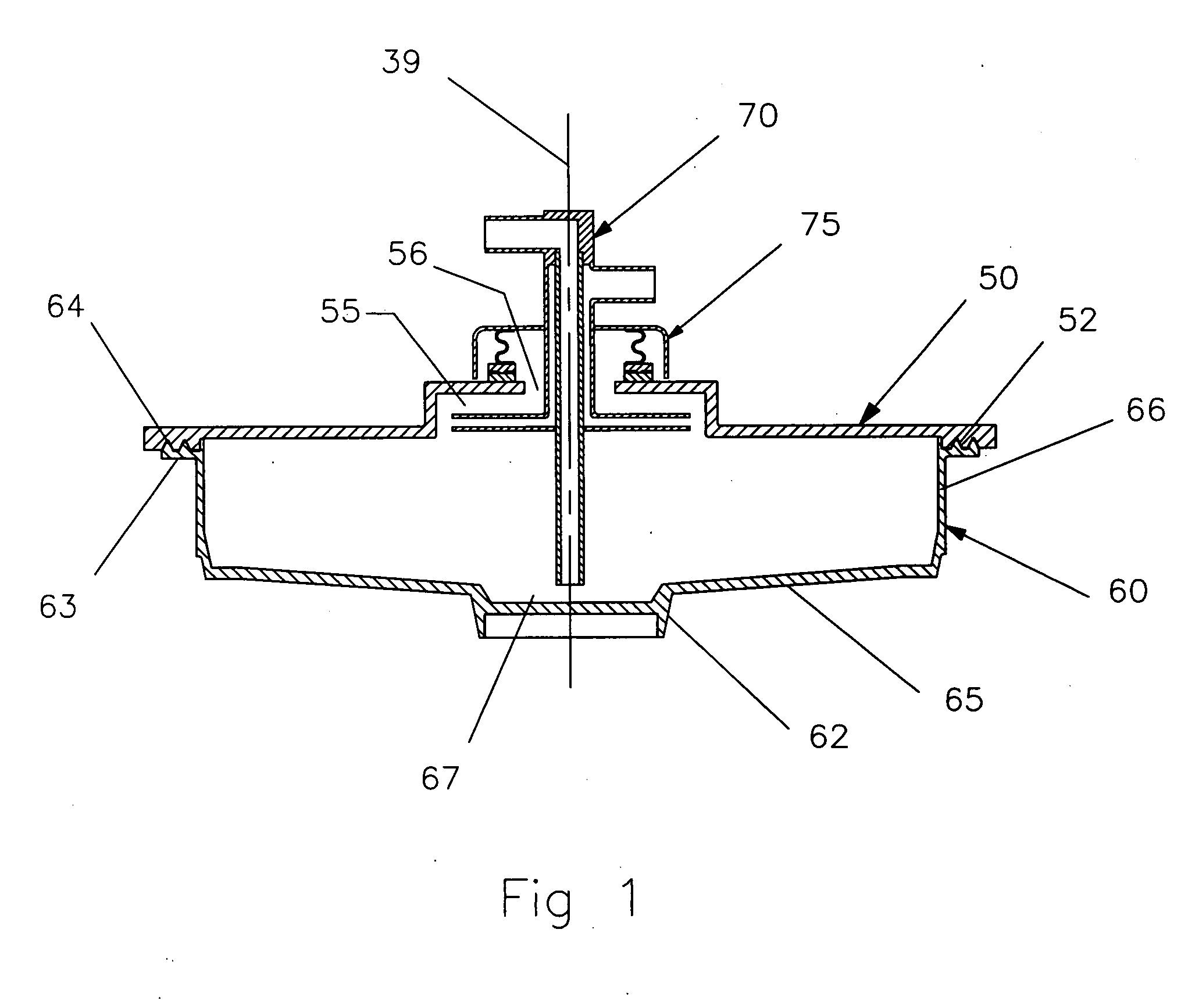
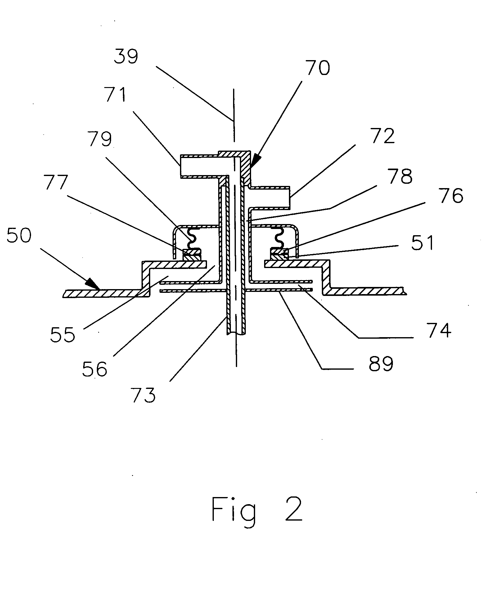
[0047]FIG. 1 shows a cross sectional view of one version of the centrifuge rotor 30 according to the present invention. The rotor 30 has an elastic body 60, which is sealed to a rigid cover 50 by bonding, welding, or other means. The rigid cover is preferably made of clear and hard plastic material such as polycarbonate. The cover typically has the shape of a circular disc with a vertical extrusion at the center forming a small cylindrical chamber 55 referred to herein after as atrium. The top section of the atrium defines a circular opening 56 at the center. The cover, the atrium and the opening are concentric and have identical axis of rotation 39.

[0048] The elastic body is preferably made of a resilient and stretchable material, such as silicone rubber. The body has stretchable vertical wall 66 connecting the base 65 to the rim 63. The rim surface has a serration 64 that is used to seamlessly join the rim to a matching geometry 52 on the periphery of the cover generating a robus...


PUM


Abstract

A rotor having variable volumes adapted for collecting and centrifuging biological fluids. The rotor includes an impermeable flexible body having a cylindrical shape with stretchable vertical walls and semi pliant base. The rotor includes a rigid circular member that is seamlessly joined to the top of the flexible body. The rigid cover defines an opening having a rotary seal that maintains a closed system inside a spinning rotor. The rotary seal permits a plurality of non-rotating conduits to pass through for controlling the flow in and out of the rotor while it is spinning. In a preferred embodiment, the rotor includes a Core to stabilize the rotating fluids inside the separation chamber, and / or includes a diverter to divert the fluid entering the rotor to the periphery of the separation chamber for better processing. When the rotor is inserted in the centrifuge, the rigid cover is fixed at the top of the centrifuge bucket. The base of the flexible body is firmly secured to the chuck by vacuum or mechanical interlock means. The chuck moves vertically down and up by pneumatics or electrical motor means embedded in the rotating centrifuge, while it is spinning. The base of the rotor moves vertically in conjunction with the chuck increasing or decreasing the volume of the processing chamber as the sidewall of the flexible body stretches or contracts. In another preferred embodiment the base of the flexible body is secured to the chuck by centrifugal means.

Description

FIELD OF THE INVENTION [0001] This invention generally relates to systems for processing blood and other biological fluids. BACKGROUND OF THE INVENTION [0002] Transfusion therapy in the past was largely dependent on the use of whole blood. While whole blood may still be used in certain limited circumstances, the modern transfusion therapy depends largely on the use of the clinically needed blood component. Whole blood consists of many components, primarily, red blood cells, white blood cells, platelets, and plasma. Therefore, there was the need for specialized equipment capable of processing drawn blood from a donor to extract the needed component and return the rest back to the donor. These equipment, known as Apheresis equipment, are largely dependent on centrifugation processes to separate blood components. These centrifugation processes are divided in tow categories, continuous flow process, and batch process. [0003] Systems utilizing continuous flow process direct the flow of t...

Claims


Application Information

Patent Timeline
Patent Type & Authority Applications(United States)
IPC IPC(8): B04B7/12
CPCB04B5/0442B04B7/00B04B2005/0485B04B2005/0464B04B11/06
Inventor CHAMMAS, JACQUES
Owner CHAMMAS JACQUES
Why Eureka
Try Eureka