High-efficiency high-voltage difference ratio bi-directional converter

a high-efficiency, bi-directional converter technology, applied in the direction of automatic control, process and machine control, instruments, etc., can solve the problems of reducing the safety of operators, affecting the operation of operators, and different life spans of batteries, so as to reduce the voltage and ensure the safety of operators

Inactive Publication Date: 2007-09-20
YUAN ZE UNIV
View PDF7 Cites 57 Cited by
  • Summary
  • Abstract
  • Description
  • Claims
  • Application Information

AI Technical Summary

Benefits of technology

[0032] In preceding mode, the freewheeling diode passage formed through the switch S1 and S2 already conducts, while in present mode it begins triggering direct conducting, current characteristics of the components maintain previous state and continue changing. The former is synchronous rectification, and for low voltage circuit with high input current, the synchronous rectification technique can drastically reduce conduction loss in freewheeling diode; and for the later, the switch is zero voltage conducting and has no switching loss. The present mode stops when the current iLS of second winding of coupled inductor Tr decreases to zero.
[0076] Although no electrical isolation, the present invention still capable of isolating electrically. According to circuit theoretic analysis, even during low voltage circuit is in open circuit state, there would be no high voltage situation occurs. If uncontrollable happens, i.e. components failure, high voltage situation occurs, due to the chosen low voltage switch S1 has low break-down voltage, it will cause the switch vDS break down and produce short-circuit current, reducing the voltage of relevant components of low voltage circuit which may be contacted by human; the short-circuit current will melt safety fuse quickly, isolating high voltage from passing to low voltage circuit and ensuring operator's safety.

Problems solved by technology

Clean energy source becomes an important subject due to oil shortage crisis.
The main drawback of serially connected batteries is that each battery has different life span and if one goes bad, the whole supply will be cut off.
Even though a few use zero-voltage or zero-current soft-switching, switching loss and conduction loss are still increased dramatically due to the current passing through too many switches.
Also, transformers are not well suited to wide range of voltage changes due to saturation of the magnetic core caused by fluctuating excited induction current and the transformer has to bear all the output power.

Method used


Image

  • High-efficiency high-voltage difference ratio bi-directional converter
  • High-efficiency high-voltage difference ratio bi-directional converter
  • High-efficiency high-voltage difference ratio bi-directional converter

Examples


Embodiment Construction

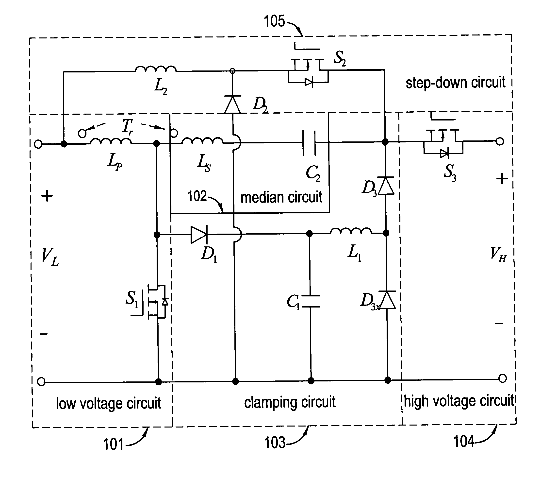
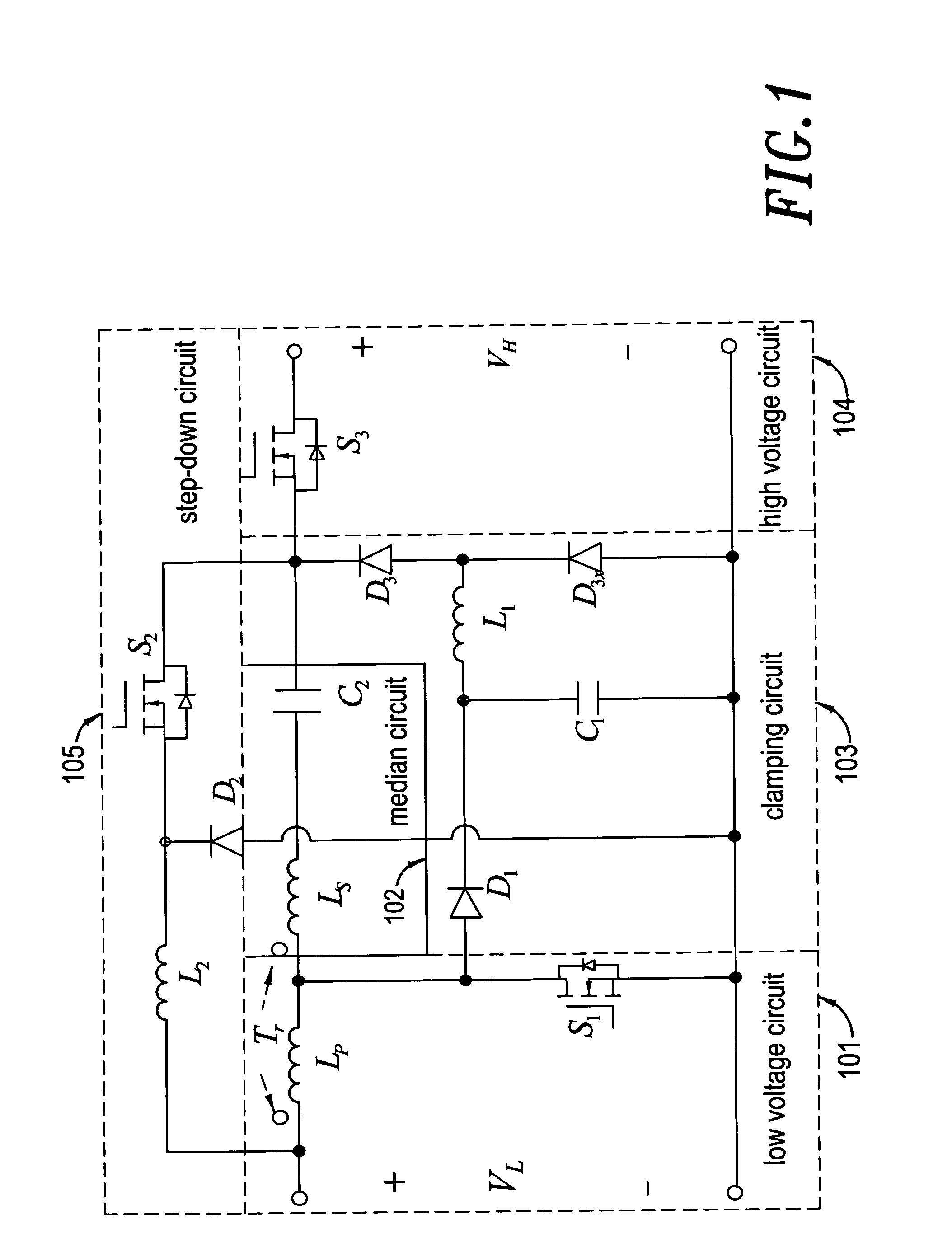
[0092] The specification of the present invention is based on high voltage circuit voltage VH=200V and low voltage circuit voltage VL=24V; it is based on consideration for application where a DC 200V power source is used for the front end of a 110V AC converter, and rechargeable batteries are used as auxiliary power source and loads, where two groups 12V DC batteries connected in series are commonly used. First step in design is to determine winding ratio of coupled inductor and switches specification. From voltage specification, GV2=1 / GV1=8.33, therefore the duty cycle d3 of high voltage switch S3 must be designed according to equation (14); at the same time, it must meet the voltage adjustment requirement of step-up / down bidirectional voltage boost gain; and by cross comparing FIG. 4 and FIG. 7, it can be determined that the winding ratio N=2. As aforementioned, in both step-up and step-down operating process, clamping capacitor C1 can absorb leakage induction energy of coupled in...


PUM


Abstract

The aim of this invention focuses on the development of a high-efficiency bidirectional converter for power sources with great voltage diversity. In traditional bidirectional converters, the circuit topology with transformer form is the common usual. Moreover, the soft-switching techniques including zero-voltage-switching (ZVS) or zero-current-switching (ZCS) are usually used for alleviating the corresponding switching losses. However, there are four and upward power semiconductor switches in these circuit schemes. By this way, it will result in the increase of production cost, and the degeneration of conversion efficiency. The coupled-inductor bidirectional scheme in the proposed converter only adopts three power semiconductor switches to accomplish the objective of bidirectional current control. Under the situation of non-isolation circuit topology, it still possesses the protection of electric safety for operators. Due to the characteristics of high step-up and step-down ratio, the battery module with low voltage could be injected into a high-voltage dc bus for the later utilization, e.g., high-voltage load, front-end of inverter. Since the techniques of voltage clamping, synchronous rectification and soft switching are manipulated in this circuit topology, and the corresponding device specifications are adequately performed, it can achieve the goal of high-efficiency bidirectional power conversion for power sources with great voltage diversity.

Description

BACKGROUND OF THE INVENTION [0001] 1. Field of the Invention [0002] The present invention is related to DC-DC conversion technology, specifically, the power system where rechargeable batteries are used as auxiliary power source, in which the voltage of the rechargeable batteries are boosted to high voltage system (or bus bar) to provide power for emergency or capacity adjustment, or in reverse charges the rechargeable batteries. [0003] 2. Description of the Prior Art [0004] Clean energy source becomes an important subject due to oil shortage crisis. New hybrid car can increase mileage and reduce oil consumption. Due to frequent switching between battery power and engine power in order to maximize fuel efficiency, high efficiency bi-directional converter becomes a critical element. Traditionally, serially connected rechargeable batteries are used in order to reduce voltage gap between battery and appliance and to avoid technical problem in high boost ratio and low conversion rate in ...

Claims


Application Information

Patent Timeline
Patent Type & Authority Applications(United States)
IPC IPC(8): H02M3/156
CPCH02M7/797H02M3/158
Inventor WAI, RONG-JONGDUAN, ROU-YONG
Owner YUAN ZE UNIV
Why Eureka
Try Eureka