Method for controlling exhaust emission control device

a technology of exhaust emission control and control device, which is applied in the direction of exhaust treatment electric control, separation process, instruments, etc., to achieve the effect of high nox reduction ratio, excellent effect and high accuracy

Inactive Publication Date: 2007-09-20
HINO MOTORS LTD
View PDF3 Cites 3 Cited by
  • Summary
  • Abstract
  • Description
  • Claims
  • Application Information

AI Technical Summary

Benefits of technology

[0014] According to the above-mentioned method for controlling an exhaust emission control device of the invention the following excellent effects and advantages can be obtained.
[0015] (I) Proper and adequate injection of the reducing agent can be realized in accordance with the volume ratios of the respective temperature zones for the catalyst. As a result NOx aareduction performance of the catalyst can be maximumly brought out to keep the NOx reduction ratio as high as possible by properly controlling the injection amount of the reducing agent; an amount of consumption of the reducing agent required can be suppressed to minimum by preventing the reducing agent from being excessively

Problems solved by technology

However in a field of automobile where safety is hard to assure as to running with ammonia itself being loaded, res

Method used


Image

  • Method for controlling exhaust emission control device
  • Method for controlling exhaust emission control device
  • Method for controlling exhaust emission control device

Examples


Embodiment Construction

[0028] An embodiment of the invention will be described in conjunction with the drawings.

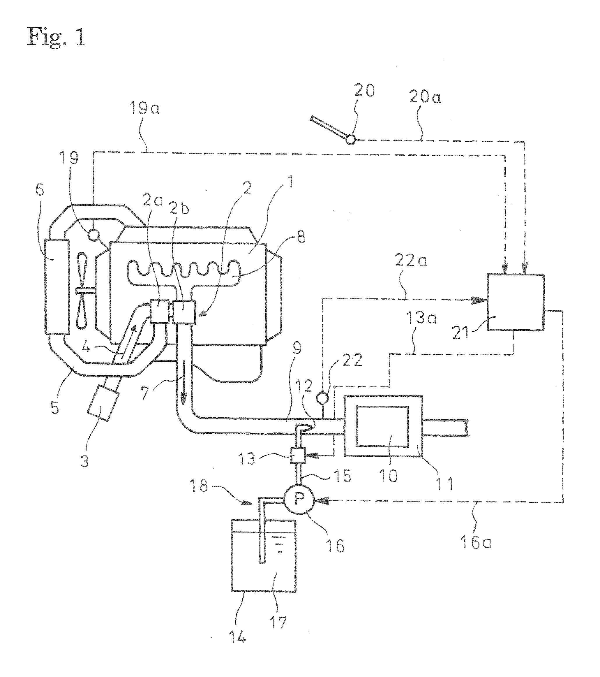
[0029]FIGS. 1-3 show the embodiment of the invention. In FIG. 1 reference numeral 1 denotes a diesel engine. The engine 1 illustrated has a turbocharger 2 with a compressor 2a to which air 4 from an air cleaner 3 is fed via an intake air pipe 5. The air 4 thus pressurized in the compressor 2a is further fed to an intercooler 6 where it is cooled. The cooled air 4 from the intercooler 6 is guided to an intake manifold (not shown) to be introduced into each of cylinders in the engine 1

[0030] Exhaust gas 7 discharged from each of the cylinders in the engine 1 is fed via an exhaust manifold 8 to a turbine 2b of the turbocharger 2. The exhaust gas 7 thus having driven the turbine 2b is discharged via an exhaust pipe 9 to outside of the vehicle.

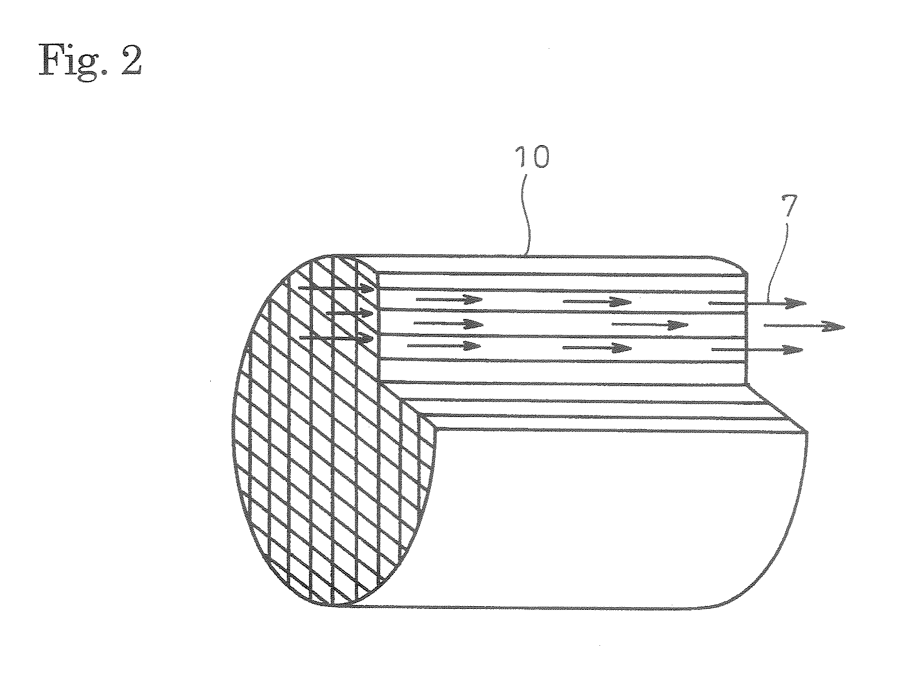
[0031] Incorporated in the exhaust pipe 9 through which the exhaust gas 7 flows is selective reduction catalyst 10 carried by a casing 11. The catalyst 10 is...


PUM

PropertyMeasurementUnit
Temperatureaaaaaaaaaa
Volumeaaaaaaaaaa
Ratioaaaaaaaaaa

Abstract

An injection amount of a reducing agent such as urea water is properly and adequately controlled to keep a NOx reduction ratio as high as possible.
Disclosed is a method for controlling an exhaust emission control device wherein urea water 17 (reducing agent) is added to selective reduction catalyst 10 incorporated in an exhaust pipe 9 so as to reduce and purify NOx. A first-order lag response model corresponding to the exhaust temperature upstream of the catalyst 10 is used to estimate catalyst temperature for each of cells into which the catalyst is minutely divided. Cell volumes for each of temperature zones are summed up on the basis of the estimated temperatures for the cells. The cell volume summation for each of the temperature zones is divided by the whole volume of the catalyst to determine temperature distribution volume ratio. The temperature distribution volume ratio for each of the temperature zones is multiplied by a reference injection amount of the urea water 17 which is determined in consideration to an operation status of a current engine 1 on the assumption that the catalyst temperatures are all within the temperature zone. The calculated values for the respective temperature zones are summed up into a directive injection amount of the urea water 17.

Description

TECHNICAL FIELD [0001] The present invention relates to a method for controlling an exhaust emission control device for reduction and purification of NOx in exhaust gas. BACKGROUND ART [0002] Conventionally, some diesel engines have selective reduction catalyst incorporated in an exhaust pipe through which exhaust gas flows, said catalyst having a feature of selectively reacting NOx with a reducing agent even in the presence of oxygen; a required amount of reducing agent is added upstream of the catalyst to be reacted with NOx (nitrogen oxides) in exhaust gas on the catalyst to thereby reduce a concentration of the discharged NOx. [0003] Meanwhile, effectiveness of ammonia (NH3) used as a reducing agent for reduction and purification of NOx is well known in a field of industrial flue gas denitration, for example, in a plant. However in a field of automobile where safety is hard to assure as to running with ammonia itself being loaded, researches have been made nowadays on use of non...

Claims


Application Information

Patent Timeline
IPC IPC(8): B01D53/86
CPCB01D53/9409B01D53/9495B01D2251/2067F01N3/208F01N9/005Y02T10/24F01N2610/02F01N2610/146F01N2900/0406F01N2900/08F01N2900/1602F01N2560/06Y02T10/12F01N3/10F01N3/18F01N9/00
Inventor TSUMAGARI, ICHIRO
Owner HINO MOTORS LTD
Why Eureka
Try Eureka