Catalytic converter and a method for producing the catalytic converter

Active Publication Date: 2007-09-27
NGK INSULATORS LTD
View PDF9 Cites 42 Cited by
  • Summary
  • Abstract
  • Description
  • Claims
  • Application Information

AI Technical Summary

Benefits of technology

[0018]The catalytic converter of the present invention, at least a part of the cells of the honeycomb structural body, which is the catalyst support thereof, are plugged so that at least a part of the fluid which flowed into the cells will flow out after passing through the porous partition walls. At the same time, by coating an air permeable catalyst coating layer, which has a predetermined average maximum distance of image and porosity, on the surface of the partition walls, at the time of passing the exhaust gas through the partition walls, the exhaust gas also passes through the catalyst coating layer so that the exhaust gas contacts efficiently with the catalytic active constituent such as the precious meta

Problems solved by technology

However, it is the fact that the sufficient catalyst performance is not obtained even by decreasing the hydraulic diameter by such increasing the cell density.
However, for producing this kind of catalytic converter actually, coating the catalyst coating layer on the inner surface of the pores of the partition walls uniformly is very difficult, and there is a problem that sufficient catalyst performance is not shown, if the uniformity of the catalyst coating layer is damaged.
Further, if trying

Method used


Image

  • Catalytic converter and a method for producing the catalytic converter
  • Catalytic converter and a method for producing the catalytic converter
  • Catalytic converter and a method for producing the catalytic converter

Examples


example 1

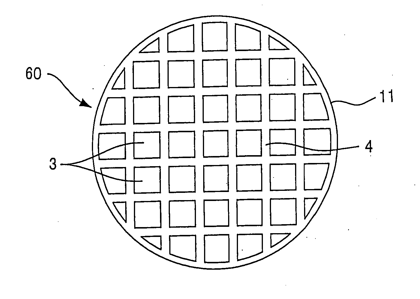
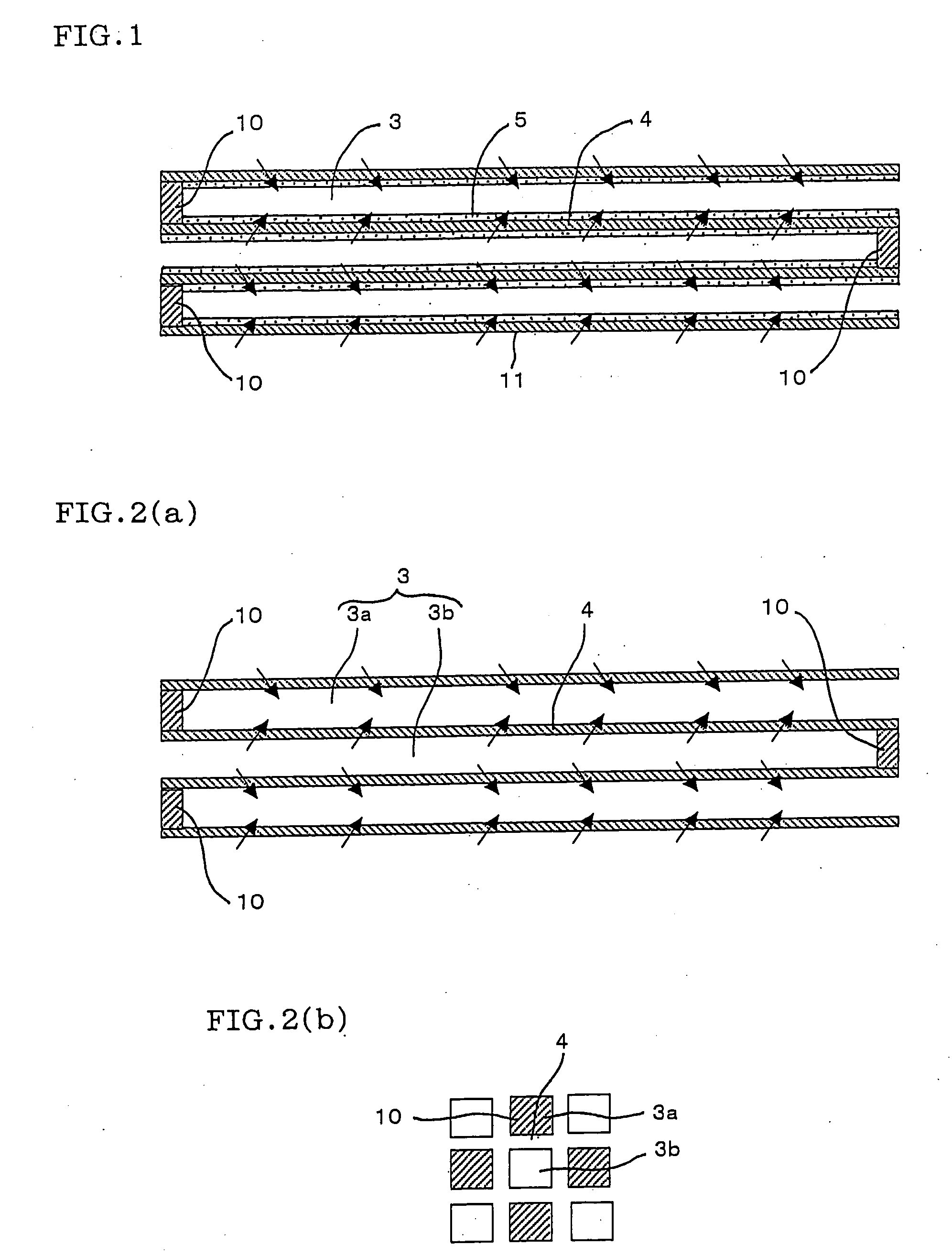
[0079]The plugging is done in the pattern as shown in FIG. 2(a) and FIG. 2(b) to the honeycomb structural body having a diameter of 105.7 mm, length of 114.2 mm, volume of 1 liter, thickness of the partition wall of 8 mil (0.203 mm), cell density of 300 cpsi (46.5 cells / cm2), the average maximum distance of image of 40 μm and the porosity of 60%. Then, the pulverized particles (the specific surface area of 50 m2 / g) having average particle diameter of 45 μm are obtained by wet pulverizing the mixture of γ Al2O3 and CeO2 having the initial average particle diameter of 150 μm by a ball mill. And Pt and Rh are supported in the pores of the pulverized particles by immersing the pulverized particles into the solution containing Pt and Rh. Next, the coating slurry is obtained by adding the foaming resin as the pore forming agent, further adding acetic acid and water to the pulverized particles which support the Pt and Rh thus obtained. Further, the slurry is coated on the partition walls b...

example 2

[0082]The catalytic converter is obtained by the same preparation process with the Example 1, except the amount of the oxides coated (γ Al2O3 and CeO2) is to be 400 g per 1 liter of the volume of the honeycomb structural body (the average thickness of the catalyst coating layer of 150 μm). About the catalytic converter, the exhaust amount of CO, HC and NOx, and the pressure loss are measured as same with the Example 1, then, the measured results are shown in Table 1 as the relative value to the measured value of the above mentioned Comparative Example 1 in which the value is expressed as 1.

examples 3-example 6

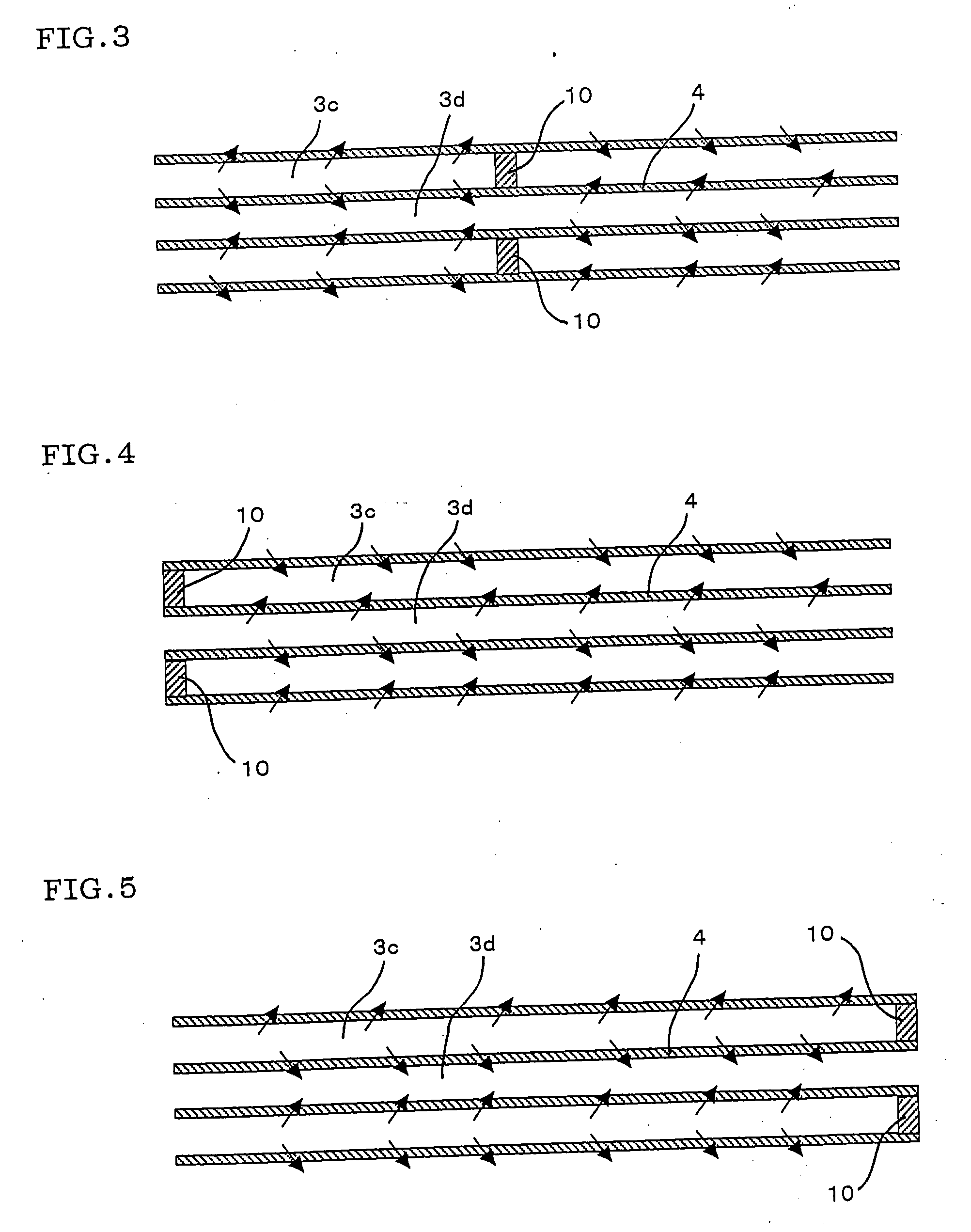
[0084]The catalytic converters are obtained by the same preparation process with the Example 2, except employing the pattern of the plugging as shown in the FIG. 3 (Example 3), FIG. 4 (Example 4), FIG. 5 (Example 5) and FIG. 6 (Example 6). About these catalytic converters, the exhaust amount of CO, HC and NOx, and the pressure loss are measured as same with the Example 1, then, the measured results are shown in Table 1 as the relative value to the measured value of the above mentioned comparative example 1 in which the value is expressed as 1.

TABLE 1Honeycomb structural bodyCatalyst coating layerAverageAveragePartitionmaximummaximumwalldistance ofOxidePtRhdistance ofPlugthicknessimagePorosityamountamountamountimagePorosityCoatingExhaust amountPressuretype(mm)(μm)(%)(g / L)(g / L)(g / L)(μm)(%)positionCOHCNOxlossExample1FIG. 2(a)0.203406015020.54560Surface of0.80.70.60.9FIG. 2(b)partitionwallCom.FIG. 2(a)0.203406015020.5535Inside of1111Example 1FIG. 2(b)pore ofpartitionwallExample 2FIG. 2(...


PUM

PropertyMeasurementUnit
Lengthaaaaaaaaaa
Fractionaaaaaaaaaa
Fractionaaaaaaaaaa

Abstract

A catalytic converter having an excellent purification efficiency and small pressure loss and a method for producing the same is provided. A catalytic converter comprises a catalyst coating layer which is coated on the surface of the partition walls of the honeycomb structural body having partition walls which divide and form a plurality of cells functioning as fluid passages. 10% or more of the plurality of the cells are plugged by the plug portions which are formed at the one end or the middle of the passage, the average maximum distance of image of the honeycomb structural body is 10 μm or more and the porosity of the honeycomb structural body is 40% or more, the catalyst coating layer contains at least one oxide selected from the group consisting of alumina, ceria, titania, silica and zirconia, and also a catalyst containing at least one precious metal selected from the group consisting of platinum, rhodium and palladium, or metal exchanged zeolite or vanadium is supported in the catalyst coating layer as the catalytic active constituent, the average maximum distance of image of the catalyst coating layer is 10 μm or more, and the porosity of the catalyst coating layer is 40% or more.

Description

TECHNICAL FIELD[0001]The present invention relates to a catalytic converter which is used suitably for purifying a treating constituent such as carbon monoxide (CO), hydro carbon (HC), nitrogen oxides (NOx) and so on contained in the exhaust gases exhausted from engines for automobile, construction machine and industrial stationary engine, and combustion apparatus, and a method for producing the same.BACKGROUND ART[0002]At the present moment, a catalytic converter is used utilizing a honeycomb structural body as the catalyst support for purifying the exhaust gases exhausted from various kinds of engines and so on. The catalytic converter has a construction in which a catalyst coating layer 5 is supported on the surface of the partition walls 4 which divide and form a plurality of cells 3 of the honeycomb structural body, as shown in FIG. 10. The catalyst coating layer 5 consists mainly of oxides such as alumina, ceria, zirconia and so on, and precious metals such as platinum, rhodiu...

Claims


Application Information

Patent Timeline
IPC IPC(8): B01D50/00B21D51/16B01D53/34
CPCB01D46/2429Y10T29/49345B01D46/2466B01D46/2474B01D2046/2433B01D2046/2437B01D2046/2496B01D2279/30B01J35/002B01J35/04B01J35/10B01J37/0018B01J37/0215B01J37/0244F01N3/2828Y10T428/24149B01D46/2459B01D46/24492B01D46/24491B01D46/2498B01D46/2482
Inventor MIYAIRI, YUKIONODA, NAOMI
Owner NGK INSULATORS LTD
Why Eureka
Try Eureka