Method to Cold-Start Fuel Cell System at Sub-Zero Temperatures

Active Publication Date: 2007-09-27
NUCELLSYS
5 Cites 13 Cited by

AI-Extracted Technical Summary

Problems solved by technology

It has been known that fuel cell systems can generate power at sub-zero temperatures (see, e.g., U.S. Pat. No. 5,798,186), but it is also known that prolonged operation at sub-zero temperatures can lead to proble...

Benefits of technology

[0017] One may use a high-performance gas burner as the burner for the method according to the invention. Such a high-performance gas burner can deliver in a short amount of time the significant amount of heat that has to be transferred to the cooling agent. In one embodiment, the high-performance gas burner has a power output in a range of approximately 30 kW to 90 kW. Depending on the desired burner output, a burner of this type requires an air mass flow rate of between approximately 50 kg/hr and 300 kg/hr during operat...

Abstract

The invention concerns a method to cold-start a fuel cell system at sub-zero temperatures, whereby the fuel cell system comprises a fuel cells stack, upstream of which is connected a heating device to heat a cooling agent to be circulated by a coolant pump. To reduce the demand for stored electrical energy, the method stipulates the following: the cold fuel cell stack is operated at such a capacity that it generates sufficient power to operate the heating device and the coolant pump; the power generated by the fuel cell stack is used to operate the heating device for heating the cooling agent as well as the coolant pump, whereby the coolant pump circulates the cooling agent between the fuel cell stack and the heating device; the heating device is switched off as soon as the fuel cell stack reaches a preset temperature that is higher than the original temperature.

Application Domain

Technology Topic

Image

  • Method to Cold-Start Fuel Cell System at Sub-Zero Temperatures
  • Method to Cold-Start Fuel Cell System at Sub-Zero Temperatures

Examples

  • Experimental program(1)

Example

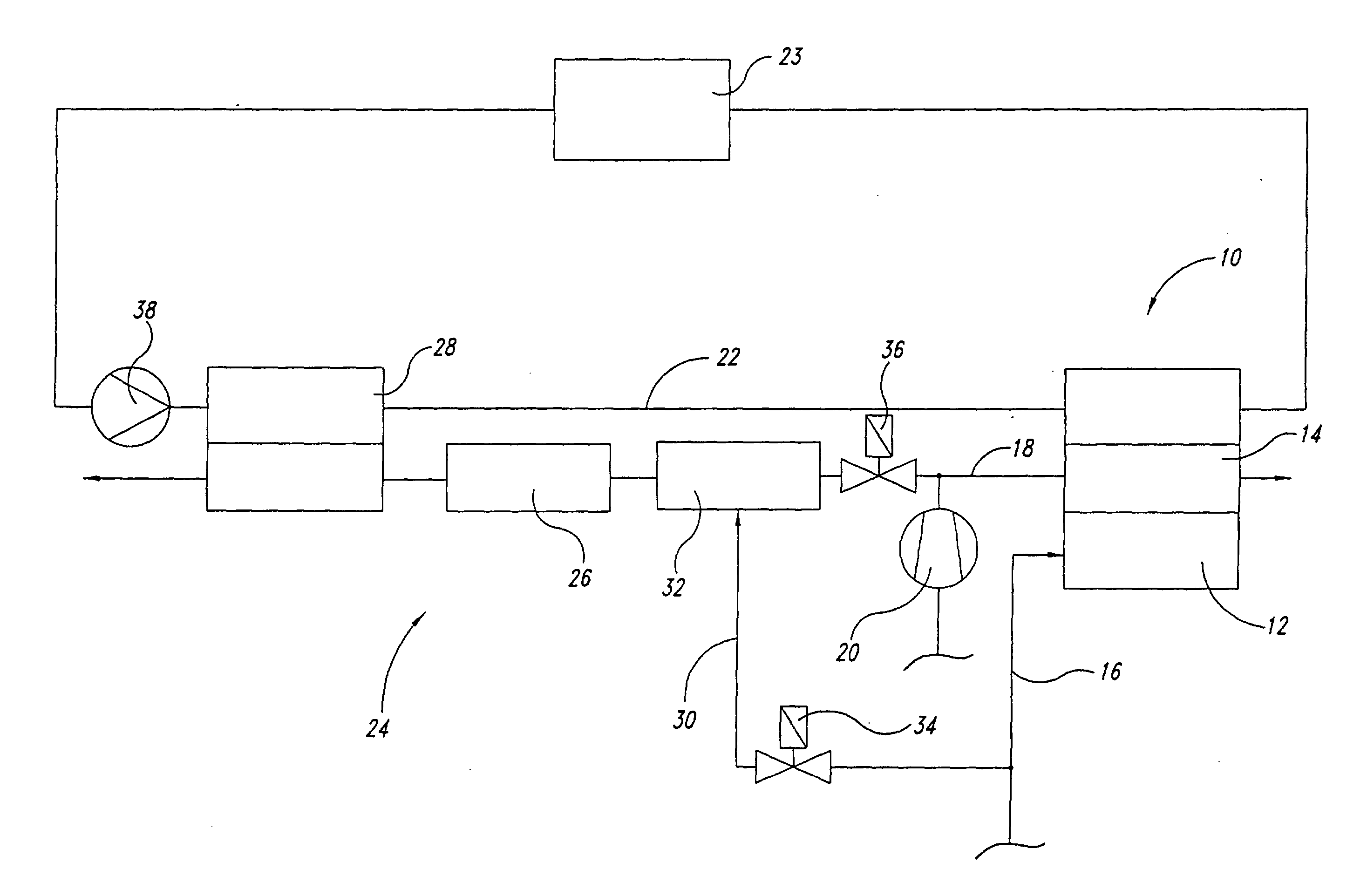
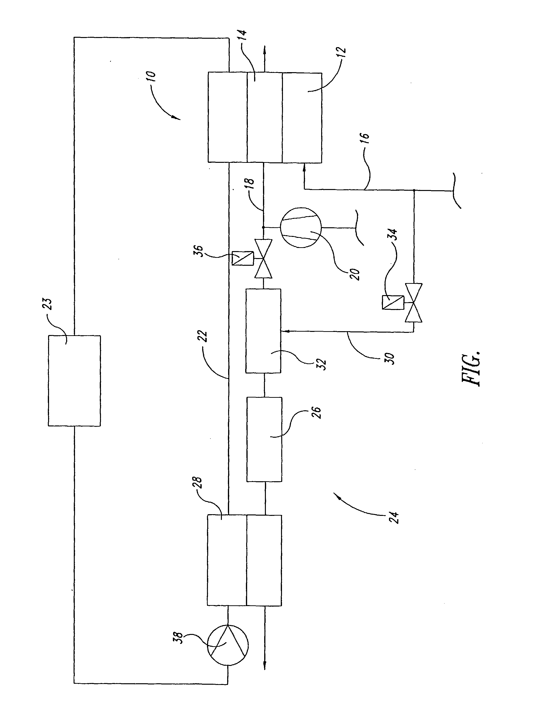
[0021] Referring to the Figure, a fuel cell stack 10 with one anode 12 and one cathode 14 are disclosed. Hydrogen is supplied to the anode 12 from a source (not shown) via a line 16. Via a line 18, the cathode 14 is supplied with oxygen in the form of air, which has been compressed by a compressor 20. In a manner known in the art, which for this reason will not be explained in more detail, the fuel cell stack 10 during its operation uses the supplied hydrogen and oxygen to produce power and water.
[0022] For the purpose of cooling the fuel cell stack 10 during its operation, the fuel cell stack 10 is connected in a heat-exchanging manner to a cooling loop 22, which uses a heat exchanger 23, which is arranged in the cooling loop 22 and is executed as a radiator, to dissipate the excess heat that is produced during the operation of the fuel cell stack 10. The cooling loop 22 also has a heat-exchanging connection to a heating device 24, which during a start-up phase supplies heat to the cooling agent circulating in the cooling loop 22, so that the fuel cell stack 10 can be heated more rapidly to operating temperature from very low ambient temperatures.
[0023] In the illustrated embodiment, the heating device 24 comprises a high-performance gas burner 26 that is operated with hydrogen and produces hot gas, whereby an additional heat exchanger 28 is used to transfer the thermal energy of the hot gas to the cooling agent circulating in the cooling loop 22. The gas burner 26 is supplied with hydrogen via a line 30, which branches off the line 16. In a mixer 32 upstream of the gas burner 26, hydrogen is mixed with the particular volume of air that is necessary to achieve proper combustion, whereby the compressor 20 delivers this air into the line 18. Control valves 34 and 36 effect the desired distribution of the hydrogen flow and the air flow between the fuel cell stack 10 and the gas burner 26 or mixer 32.
[0024] A coolant pump 38 is responsible for circulating the cooling agent through the cooling loop 22. As shown in the Figure, the cooling loop 22 typically is a closed loop. In the shown embodiment example, the heat exchanger 23 used to cool the cooling agent during operation is a different heat exchanger than the heat exchanger 28 that is used to heat the cooling agent during the start-up phase, but it is also possible for the heat exchangers 23 and 28 to employ common components or to be integrated into each other.
[0025] The illustrated arrangement operates as follows. At first the compressor 20 is started with the help of a battery (not shown) and the hydrogen supply via the line 16 is opened, so that air and hydrogen are fed to the fuel cell stack 10. The fuel cell stack 10 commences operation and is set by its control system to operate at low load, e.g., at approximately 10% of its rated power. The power generated by the fuel cell stack 10 is now used to drive the compressor 20, the coolant pump 38, as well as all auxiliaries necessary for the operation of the heating device 24 and the fuel cell stack 10. The heating device 24, in particular its gas burner 26, is started and the hot gas generated by it heats the cooling agent in the cooling loop 22, which is circulated through the cooling loop 22 by the coolant pump 38. In this operating state, the heat exchanger 23 is not operating, i.e., either it is not supplied with cooling agent or the cooling agent circulating in the cooling loop 22 is carried past the heat exchanger 23, for example by means of a bypass line (not shown) that bypasses the heat exchanger 23.
[0026] As soon as the fuel cell stack 10 has reached the temperature required for normal operation, for example +5° C., the gas burner 26 is switched off and the fuel cell stack 10 can be operated at a higher load, or at full load, if required. In this operating state the cooling loop 22 serves its actual purpose, namely cooling the fuel cell stack 10 by means of the heat exchanger 23.
[0027] In the following, we will use an example to further explain the application of the method of the present invention in a fuel cell system.
[0028] For the experiment, we employed a polymer-electrolyte-membrane fuel cell stack with an output power of approximately 85 kW. This fuel cell stack can be operated for approximately 3 to 4 minutes at −15° C. and at a load of approximately 5% to 10% of its nominal output power (i.e., with an output power of approximately 4 to 7 kW), before one faces problems due to ice formation or similar factors.
[0029] According to the method of the invention, the fuel cell system only has to be supplied with a quantity of heat that is sufficient to heat the fuel cell stack from −15° C. to a temperature from which the fuel cell stack can reach its operating temperature on its own without outside help. In the fuel cell systems under investigation, this temperature was assumed to be +5° C. To be able to carry out three to four subsequent start-up processes in rapid succession, each of the start-up processes has to be completed in less than approximately 1 minute.
[0030] To heat the fuel cell stack from −15° C. to +5° C., one has to introduce a computed quantity of heat between 1800 and 2200 kJ into the cooling agent. It is desirable to transfer this amount of heat to the cooling agent within approximately 40 seconds, so that during the remaining 20 seconds the cooling agent can transfer the absorbed heat to the actual fuel cell stack. The listed requirements translate into a power of approximately 45 to 55 kW, which the burner has to be able to generate and the heat exchanger has to be able to transfer. For the burner to generate this quantity of heat, approximately 200 kg/hr of air has to be carried to the burner and subsequently to the heat exchanger. Assuming that an additional 3 to 50 kg/hr of air has to be supplied to the fuel cell stack during the same time period in order for the fuel cell stack to generate the required electrical power, the compressor has to be able to deliver a flow of approximately 230 to 250 kg/hr during the start-up process. In dependence on the pressure gradient that the compressor has to produce, this corresponds to approximately 2 to 5 kW of electrical power that has to be supplied to the compressor. Added to this must be the electrical power of approximately 800 W required by the coolant pump and the approximately 500 W that is needed by additional loads, such as sensors, control systems, etc., so that the fuel cell stack has to generate approximately 3½ to 6½ kW of electrical power during the start-up process.
[0031] As explained above, the fuel cell stack is able to generate an output power of this level already during the start-up process, which makes it possible to use a smaller starter battery. A starter battery that only has to be able to start the fuel cell stack needs an output power of not more than 1.5 kW for less than 5 seconds, whereas a battery that also has to provide power during a cold-start process has to be able to provide a power output of at least approximately 6 kW for up to 60 seconds. A 1.5 kW battery is significantly smaller and less expensive than a 6 kW battery, and further evidences an advantage of this invention.
[0032] The above-mentioned embodiment examples and application examples are to be considered only as examples. It goes without saying that in particular the listed numerical values can differ from one fuel cell system to the next fuel cell system in dependence on the chosen design and the nominal output power.
[0033] All of the above U.S. patents, U.S. patent application publications, U.S. patent applications, foreign patents, foreign patent applications and non-patent publications referred to in this specification and/or listed in the Application Data Sheet, are incorporated herein by reference, in their entirety.

PUM

no PUM

Description & Claims & Application Information

We can also present the details of the Description, Claims and Application information to help users get a comprehensive understanding of the technical details of the patent, such as background art, summary of invention, brief description of drawings, description of embodiments, and other original content. On the other hand, users can also determine the specific scope of protection of the technology through the list of claims; as well as understand the changes in the life cycle of the technology with the presentation of the patent timeline. Login to view more.

Similar technology patents

Classification and recommendation of technical efficacy words

Why Eureka
Try Eureka