Electrical Connector For A Window Pane Of A Vehicle

a technology for electrical connectors and window panes, applied in the direction of coupling device connections, soldering apparatus, manufacturing tools, etc., can solve the problems of poor solderability, environmental contamination, cracking or other damage to substrates, etc., to reduce mechanical stress, reduce bending, breakage or delamination, and resist delamination from the substrate

Inactive Publication Date: 2007-09-27
AGC AUTOMOTIVE AMERICAS
View PDF4 Cites 166 Cited by
  • Summary
  • Abstract
  • Description
  • Claims
  • Application Information

AI Technical Summary

Benefits of technology

[0012] The subject invention provides a window pane. The window pane includes a substrate. The subject invention also provides an electrical device for a window pane, and a vehicle including the window pane. The window pane includes an electrical conductor applied across a region of the substrate. An electrical connector is bonded to the electrical conductor and has a first interacting portion. A terminal is disposed adjacent to the electrical connector and has a second interacting portion for interacting with the first interacting portion to mechanically couple the electrical connector and the terminal. Due to the mechanical coupling between the connector and the terminal, the terminal is less prone to bending, breakage, or delamination than conventional connector structures that include an integral terminal. Also, since the terminal and connector are mechanically coupled, a low stress concentration is also achievable between the connector and the terminal.
[0013] The substrate has a first coefficient of thermal expansion and the connector has a second coefficient of thermal expansion. A difference between the first and second coefficients of thermal expansion is equal to or less than 5×10⁻⁶/° C. for minimizing mechanical stress between the connector and the substrate due to thermal expansion of the connector and the substrate resulting from changes in tem

Problems solved by technology

Such stress may result in cracking or other damage to the substrate, which is typically made of glass.
However, it is known that lead may be considered an environmental contaminant.
However, such materials have increased radical reaction rates between the tin-rich solder and the silver conductor, resulting in poor solderability.
These conventional materials do not absorb the mechanical stress between the connector and the substrate due to thermal expansion of the connector and the substrate resulting from changes in temperature, which tends to crack or otherwise damage the substrate.
Further, many alternative materials for the connector are difficult to solder, making it difficult to sufficiently adhere the connector to the conductor on the substrate.
However, solder compositions including indium may have very soft phases, and the solder compositions exhibit poor cohesive strength under stress.
Because these other conventional materials are insufficient, there has been little movement in the automotive industry away from soldering the connectors with solder including lead.
Although there has been development of various conductors for use in the window panes of vehicles, such developments have little applicability to electrical connector technology.
The titanium-containing conductor in the '026 patent cannot effectively function as a connector that connects a power supply to a conductor that is bonded to one of the glass panes.
The titanium core with the outer surface including copper is ineffective for use as an electrical connector due to the presence of the copper because the copper would delaminate from

Method used


Image

  • Electrical Connector For A Window Pane Of A Vehicle
  • Electrical Connector For A Window Pane Of A Vehicle
  • Electrical Connector For A Window Pane Of A Vehicle

Examples


examples

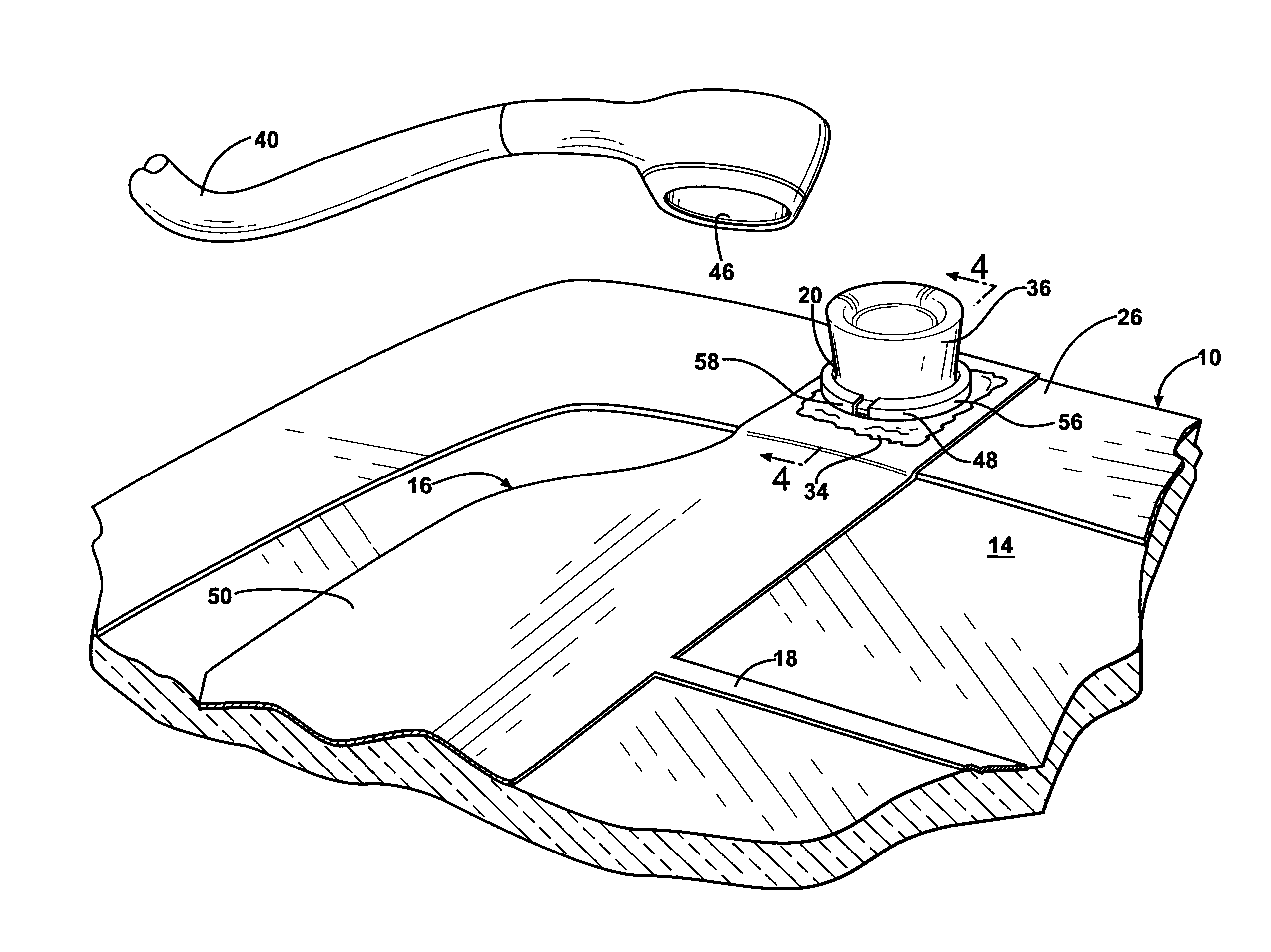
[0051] Test plaques were made including the glass substrate 14, the electrical conductor 16, the electrical connector 20 including the layer of solderable metal 32, and the layer of solder 34. Half of the test plaques include glass substrates 14 with a ceramic layer 26, and the electrical conductor 16 was bonded to the glass substrate 14 over the ceramic layer 26. However, the results were the same for both configurations with and without the ceramic layer 26 present. The electrical conductor 16 was formed from silver paste for all of the plaques, and the silver paste was fired onto the substrate 14 to form the electrical conductor 16. The layer of solderable metal 32 was formed on the connector 20 by vacuum ion plating. The connector 20 was soldered to the conductor 16 through the layer of solder 34. The electrical connector 20, the layer of solderable metal 32, and the layer of solder 34 were formed from metals as indicated in Table 1. The glass substrate 14 was formed from soda-l...


PUM

PropertyMeasurementUnit
Percent by massaaaaaaaaaa

Abstract

A window pane has a substrate formed from glass and includes an electrical device including an electrical conductor. An electrical connector is operatively connected to and in electrical communication with the conductor for transferring electrical energy to the conductor. An electrical connector is bonded to the electrical conductor and has a first interacting portion. A terminal is disposed adjacent to the electrical connector and has a second interacting portion for interacting with the first interacting portion to mechanically couple the electrical connector and the terminal. The substrate has a first coefficient of thermal expansion and the connector has a second coefficient of thermal expansion. A difference between the first and second coefficients of thermal expansion is equal to or less than 5×10⁻⁶/° C. Due to the mechanical coupling between the connector and the terminal, the terminal and connector are less prone to bending, breakage, or delamination than conventional connector structures.

Description

RELATED APPLICATIONS [0001] This patent application is a continuation-in-part of and claims priority to and all advantages of U.S. patent application Ser. No. 11 / 619,081, which was filed on Jan. 2, 2007 and which is a continuation-in-part of and claims priority to an all advantages of U.S. patent application Ser. No. 10 / 988,350, which was filed on Nov. 12, 2004.BACKGROUND OF THE INVENTION [0002] 1. Field of the Invention [0003] The subject invention generally relates to a window pane of a vehicle that includes an electrical connector and an electrical conductor. More specifically, the subject invention relates to an electrical connector that transfers electrical energy to an electrical conductor of the window pane, such as a defogger, defroster, antenna, etc. [0004] 2. Description of the Related Art [0005] Electrical connectors are known in the art for use in vehicles. The connectors are soldered to and in electrical communication with an electrical conductor for transferring electr...

Claims


Application Information

Patent Timeline
IPC IPC(8): H01R33/00
CPCH01R4/02H01R4/10H01R11/11H01R13/03H01R13/22H05B3/84H01R12/707B23K35/262B23K35/264B32B15/01C22C12/00C22C13/00H05B2203/016
Inventor HOEPFNER, TIMOTHY P.SATO, MAKOTO
Owner AGC AUTOMOTIVE AMERICAS
Why Eureka
Try Eureka