
Resin Composite Hose of Curved Shape and Method for Producing the Same

a composite hose and curved technology, applied in the direction of filament/thread forming, chemistry apparatus and processes, mechanical instruments, etc., can solve the problems of large force required for fitting or slipping the hose on the mating pipe, hard resin layer, insufficient sealing properties, etc., to prevent deformation behavior, smooth removal, and prevent the effect of deformation behavior

Inactive Publication Date: 2007-10-04
SUMITOMO RIKO CO LTD
View PDF12 Cites 10 Cited by
  • Summary
  • Abstract
  • Description
  • Claims
  • Application Information

AI Technical Summary

Benefits of technology

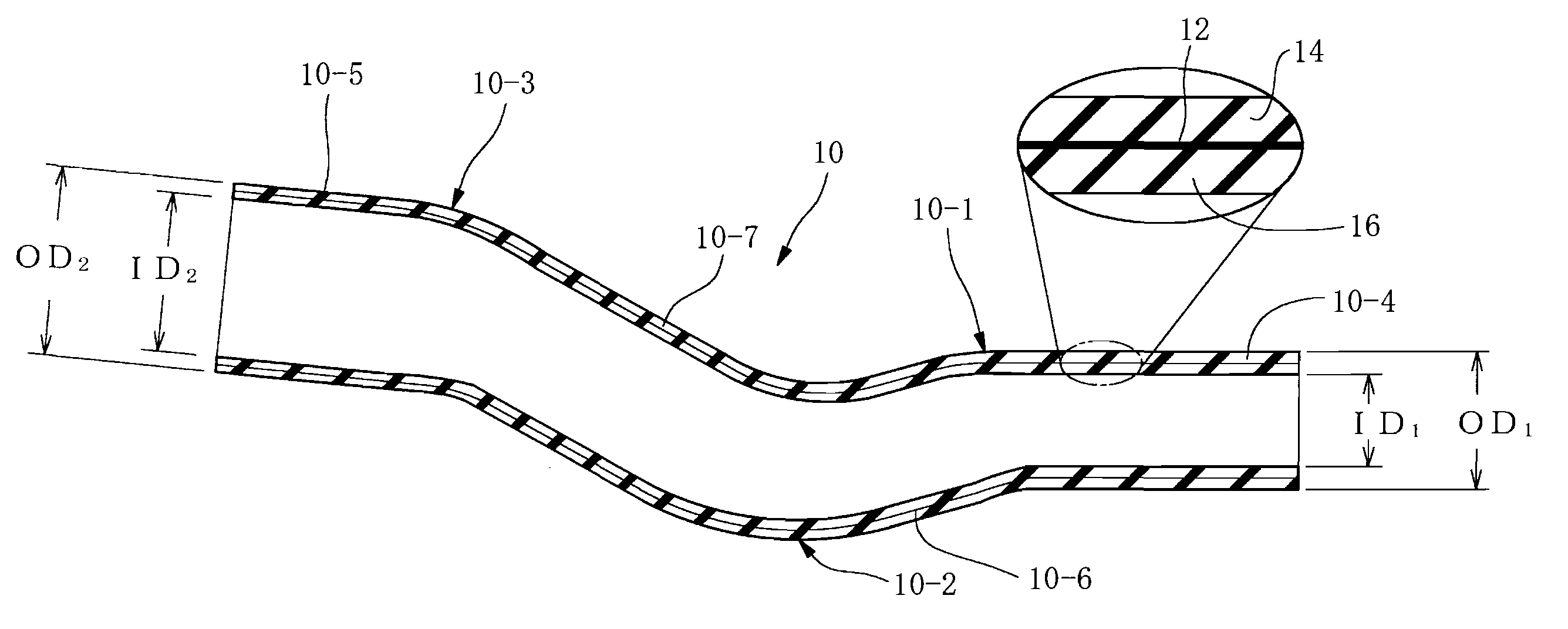
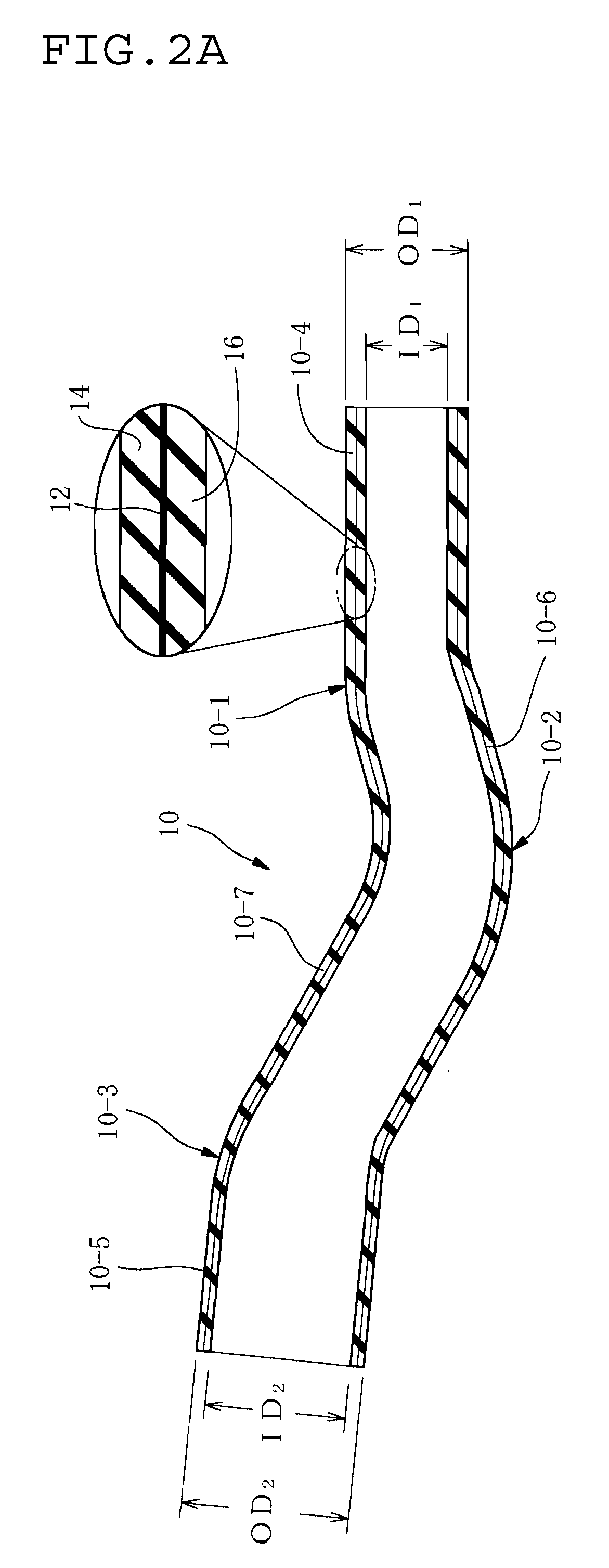
[0052]Here, according to the present invention, the curved portion has a shape of continuously increasing diameter along the axial direction of the resin composite hose. Therefore, during fitting of the tubular hose body on the mandrel, an excess length, namely slack or loosening created on the inner side of the curved portion is absorbed, offset or eliminated by increasing diameter of the curved portion. That is, slack or loosening is absorbed or offset by elongation of the resin layer in a circumferential direction due to forcedly increasing diameter of the resin layer. As a result, the resin layer is prevented from above wave-shaped deformation behavior on the inner side of the curved portion, and thereby the rubber layer is also prevented from deformation behavior.
[0054]According to one aspect of the present invention, the resin composite hose has a plurality of the curved portions at certain axial positions, and the plurality of the curved portions are arranged in order of increasing diameter from the other axial end of the resin composite hose toward the one axial end thereof. The curved portions have different diameters, respectively. The curved portions are arranged such that the curved portion near the one axial end is larger in diameter than the curved portion near the other axial end in any two adjacent curved portions. In this configuration, above wave-shaped deformation behavior can be favorably prevented on each of the curved portions. At the same time, during production procedure, the unvulcanized or semivulcanized straight tubular hose body can be fitted and deformed on the mandrel favorably with no difficulty. And, after vulcanizing step, the resin composite hose can be smoothly removed relatively from the mandrel with no difficulty.
[0055]The method for producing the resin composite hose of curved shape according to the present invention comprises a step of forming an unvulcanized or semivulcanized plastically deformable straight tubular hose body of multilayer construction by successively laminating the inner rubber layer, the resin layer and the outer rubber layer on one another by extrusion, a step of preparing a mandrel having the curved shape, a step of relatively fitting the straight tubular hose body on the mandrel and deforming the straight tubular hose body to obtain a curved tubular hose body, and a step of vulcanizing the curved tubular hose body to obtain the resin composite hose of curved shape. In this production method, above resin composite hose of curved shape can be easily produced in a small number of steps, and therefore can be provided at much lower cost than before.

Problems solved by technology

However, the resin layer as the barrier layer is hard since resin is a material harder than rubber.
So, in a hose including the resin layer laminated on an inner side of the outer rubber layer to an extreme end thereof (an axial end of the hose), when the hose is fitted on a mating pipe, a sealing property becomes insufficient due to poor bonding between the mating pipe and the resin layer that defines an inner surface of the hose.
And, since the resin layer defining the inner surface of the hose is hard and has a large deformation resistance, a great force is required for fitting or slipping the hose on the mating pipe.
This causes a problem that easiness of connection of the hose and the mating pipe is impaired.
However, in case of the resin composite hose 200 shown in FIG. 8, such production method cannot be employed.
However, the inventors test-produced a resin composite hose of curved shape in this manner, and found that the following problem was caused.

Method used


Image

  • Resin Composite Hose of Curved Shape and Method for Producing the Same
  • Resin Composite Hose of Curved Shape and Method for Producing the Same
  • Resin Composite Hose of Curved Shape and Method for Producing the Same

Examples


Embodiment Construction

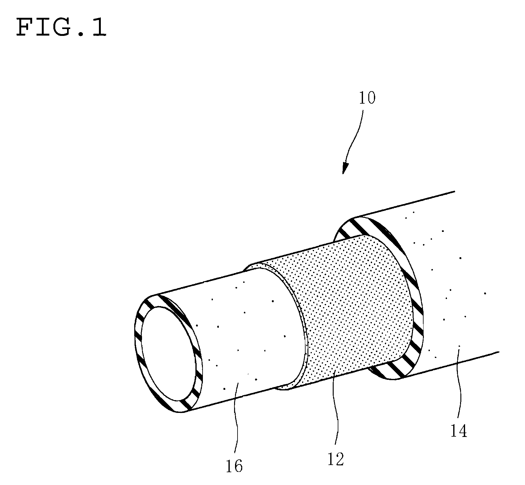
[0072]In FIGS. 1 and 2, reference numeral 10 indicates a resin composite hose (hereinafter simply referred to as a hose) as a fluid transporting hose that is suitable for a hose such as a fuel hose. The hose 10 has multilayer construction comprising a resin layer 12 as a barrier layer having a permeation resistance to a transported fluid, an outer rubber layer 14 on an outer side of the resin layer 12, and an inner rubber layer 16 as an inner surface layer on an inner side of the resin layer 12.

[0073]Here, the resin layer 12 as a middle layer is formed to extend from one axial end to the other axial end of the hose 10, or to extend from one axial edge portion to the other axial edge portion thereof.

[0074]In this embodiment, acrylonitrile butadiene rubber (NBR) is used for the inner rubber layer 16, fluorothermoplastic copolymer consisting of at least three monomers, tetrafluoroethylene, hexafluoropropylene, and vinylidene fluoride (THV) is used for the resin layer 12, and NBR+PVC is...


PUM

PropertyMeasurementUnit
Diameteraaaaaaaaaa
Electrical resistanceaaaaaaaaaa
Shapeaaaaaaaaaa

Abstract

A resin composite hose of curved shape includes a resin layer having permeation resistance to a transported fluid and serving as a barrier layer, an inner rubber layer as an inner surface layer on an inner side of the resin layer and an outer rubber layer on an outer side of the resin layer. The resin composite hose has one axial end that is larger in diameter than the other axial end thereof. The resin composite hose has at least one curved portion. The curved portion is formed in a shape of progressively and continuously increasing diameter from a curve beginning end with a small diameter near the other axial end of the resin composite hose to a curve terminal end with a large diameter near the one axial end thereof.

Description

BACKGROUND OF THE INVENTION[0001]1. Field of the Invention[0002]The present invention relates to a resin composite hose of curved shape including a resin layer that is disposed in the middle of multilayers, has a permeation resistance to a transported fuel and serves as a barrier layer, and a method for producing such a resin composite hose of curved shape.[0003]2. Description of the Related Art[0004]For application of a fluid transporting hose, for example, a fuel hose in a motor vehicle, a typical rubber hose made of a blend of acrylonitrile-butadiene rubber and polyvinyl chloride (NBR / PVC blend, NBR+PVC) or the like has been conventionally used. Such rubber hose has a high vibration-absorbability, easiness of assembly, and an excellent permeation resistance to a fuel (gasoline).[0005]However, recently, in view of global environmental conservation, regulations on restriction of permeation of motor vehicle fuel has been tightened, and demand for fuel permeation resistance is expect...

Claims


Application Information

Patent Timeline
IPC IPC(8): F16L9/00B29C47/06B29C47/20B29C48/09B29C48/21B29C48/32
CPCB29C47/0023B29C47/0035F16L2011/047F16L11/12B29C47/065B29C48/09B29C48/131B29C48/21
Inventor SAKAZAKI, KAZUSHIGETSUNETOMO, KOHEI
Owner SUMITOMO RIKO CO LTD
Learn More