Plasma processing apparatus and plasma processing method

a processing apparatus and plasma technology, applied in the direction of coatings, chemical vapor deposition coatings, electric discharge tubes, etc., can solve the problems of considerable deterioration of the surface uniformity of the process, reduce the ground capacitance of the inner electrode, increase the plasma density of the electrode edge portion, and reduce the plasma density

Active Publication Date: 2007-10-04
TOKYO ELECTRON LTD
View PDF13 Cites 10 Cited by
  • Summary
  • Abstract
  • Description
  • Claims
  • Application Information

AI Technical Summary

Benefits of technology

[0019] Further, in accordance with another embodiment of the present invention, the first electrode is partitioned into a disk-shaped inner electrode and a ring-shaped outer electrode in a radial direction, a fourth insulator of a ring shape is inserted between the inner electrode and the outer electrode, and a fifth insulator of a ring shape is inserted between the outer electrode and the sidewall of the processing vessel. With this configuration, the ground capacitance of the inner electrode can be reduced remarkably, and the effect of relatively decreasing the plasma density at the electrode central portion to thereby relatively increase the plasma density of the electrode edge portion can be magnified.
[0020] In accordance with the plasma processing apparatus or the plasma processing method, it is possible to, by means of the above-described configurations and functions, uniformize or control a spatial density distribution of plasma generated by a capacitively coupled radio frequency discharge. Thus, the in-surface uniformity in the plasma process can be improved.

Problems solved by technology

As a result, there occurs a problem that an in-surface uniformity of the process is considerably deteriorated.

Method used


Image

  • Plasma processing apparatus and plasma processing method
  • Plasma processing apparatus and plasma processing method
  • Plasma processing apparatus and plasma processing method

Examples


Embodiment Construction

[0038] Hereinafter, embodiments of the present invention will be described with reference to the accompanying drawings.

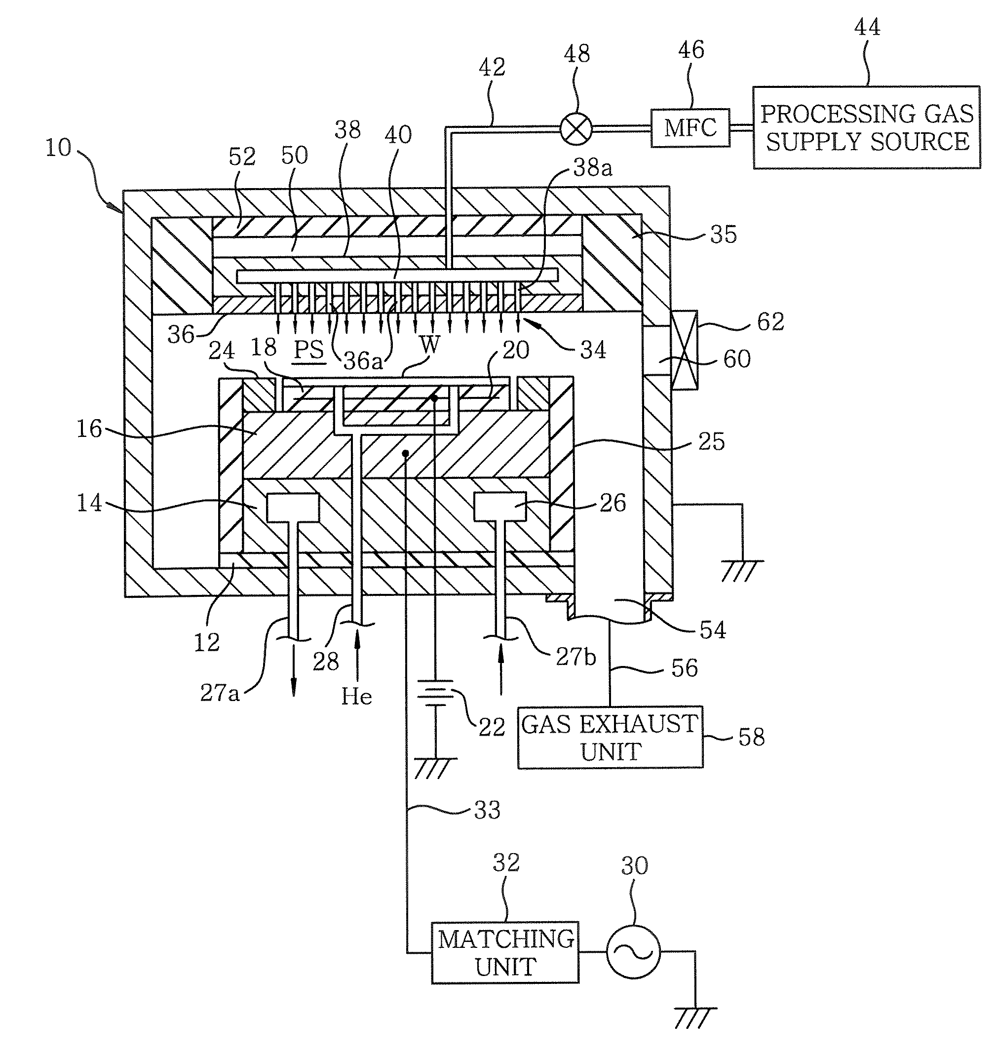
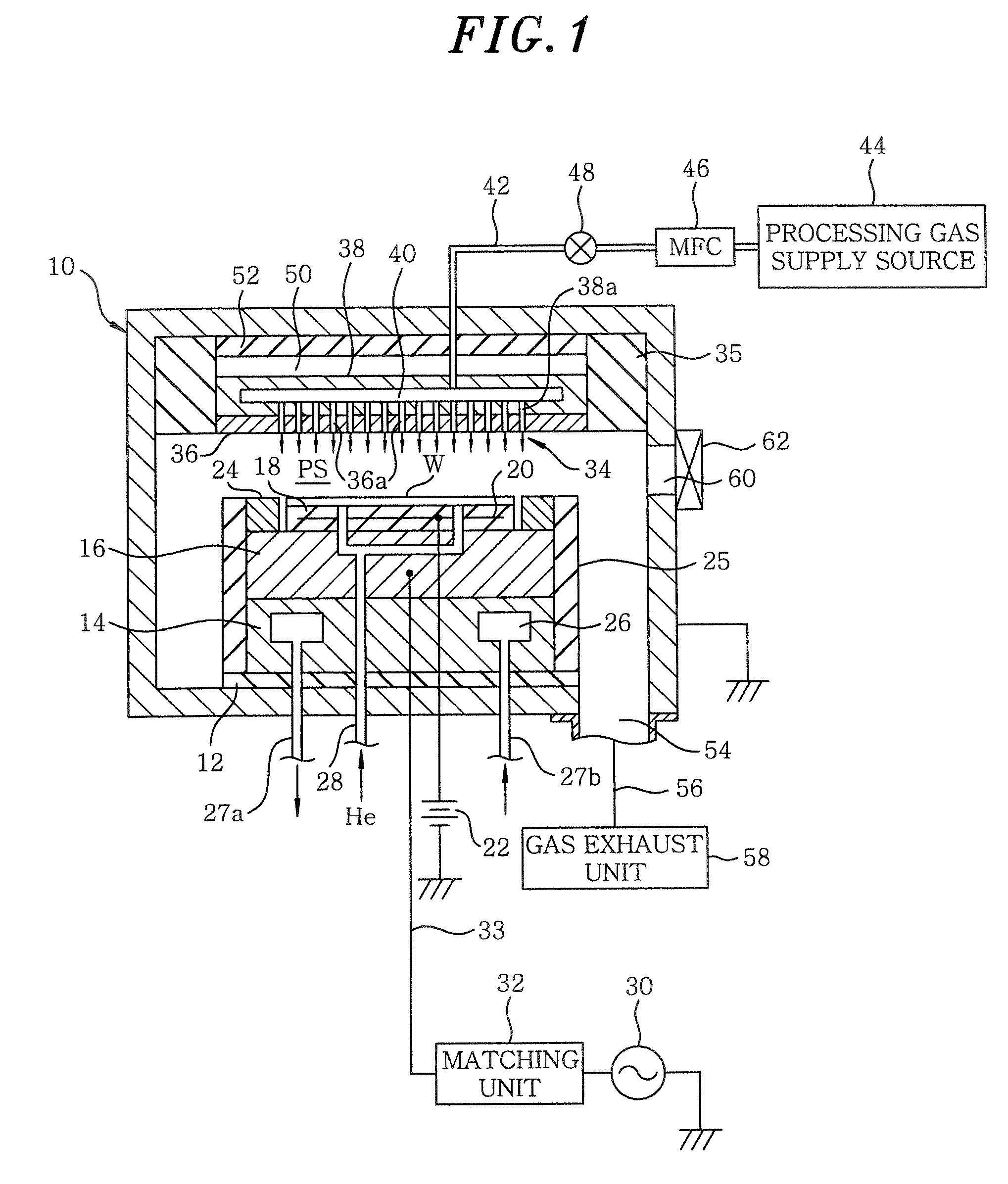
[0039]FIG. 1 illustrates a configuration of a plasma processing apparatus in accordance with an embodiment of the present invention. The plasma processing apparatus is configured as a capacitively coupled (parallel plate type) plasma processing apparatus of a cathode coupling type. The plasma processing apparatus has a cylindrical vacuum chamber (processing chamber) 10 made of, e.g., an aluminum whose surface is alumite-treated (anodically oxidized), and the chamber 10 is frame grounded.

[0040] A cylindrical susceptor support 14 is provided at a bottom portion in the chamber 10 via an insulation plate 12 made of ceramic or the like. Further, a susceptor 16 made of, e.g., aluminum, is disposed above the susceptor support 14. The susceptor 16 serves as a lower electrode and a target substrate, e.g., a semiconductor wafer W, is mounted thereon.

[0041] On the top surfa...


PUM

PropertyMeasurementUnit
electrostatic capacitanceaaaaaaaaaa

Abstract

A plasma processing apparatus includes a processing vessel capable of being vacuum evacuated; a first electrode disposed in the processing vessel in a state electrically floating via an insulating member or a space; a second electrode, arranged in the processing vessel to face and be in parallel to the first electrode with a specific interval, supporting a substrate to be processed; a processing gas supply unit for supplying a desired processing gas into a processing space surrounded by the first electrode, the second electrode and a sidewall of the processing vessel; and a first radio frequency power supply unit for applying a first radio frequency power to the second electrode to generate a plasma of the processing gas in the processing space. An electrostatic capacitance between the first electrode and the processing vessel is set such that a desired plasma density distribution is obtained for the generated plasma.

Description

CROSS-REFERENCE TO RELATED APPLICATIONS [0001] This document claims priority to Japanese Patent Application No. 2006-92860, filed on Mar. 30, 2006 and U.S. Provisional Application No. 60 / 791,460, filed on Apr. 13, 2006, the entire content of which are hereby incorporated by reference.FIELD OF THE INVENTION [0002] The present invention relates to a technique for performing a plasma processing on a substrate to be processed; and, more particularly, to a capacitively coupled plasma processing apparatus and a plasma processing method. BACKGROUND OF THE INVENTION [0003] In a manufacturing process of semiconductor devices or flat panel displays (FPDs), a plasma is used to perform a processing, such as etching, deposition, oxidation, sputtering or the like, so as to obtain a good reaction of a processing gas at a relatively low temperature. Conventionally, a capacitively coupled type plasma apparatus has been widely employed as a single-wafer plasma processing apparatus, especially, as a s...

Claims


Application Information

Patent Timeline
Patent Type & Authority Applications(United States)
IPC IPC(8): C23F1/00C23C16/00
CPCH01J37/32174H01J37/32091
Inventor MATSUMOTO, NAOKIHAYAKAWA, YOSHINOBUHANAOKA, HIDETOSHIKODAMA, NORIAKIKOSHIMIZU, CHISHIOIWATA, MANABUTANAKA, SATOSHI
Owner TOKYO ELECTRON LTD
Why Eureka
Try Eureka