Method and Apparatus for Processing Powder and Method of Manufacturing Porous Granulated Substance

a technology of porous granulated substance and processing method, which is applied in the direction of granulation using vibration, granulation in rotating dishes/pans, grain treatment, etc., can solve the problems of requiring a large amount of processing time, complicated processing apparatus, and difficult for any of these methods alon

Inactive Publication Date: 2007-10-04
HOSOKAWA MICRON CORP
View PDF0 Cites 9 Cited by
  • Summary
  • Abstract
  • Description
  • Claims
  • Application Information

AI Technical Summary

Benefits of technology

[0065] Further, as the moving means acts on the container member as the target of its rotational driving and the oscillating means acts on another processing member as its target of oscillating driving other than the target of rotational driving, each means can be simplified.
[0066] Further, in the porous granulated substance manufacturing method described so far, by setting various conditions such as the width of the gap formed between the accumulating face and the processing face, the speed of the relative movement and the oscillation frequency between the accumulating face and t

Problems solved by technology

In the case of the powder processing methods described in the above-described Prior-Art Documents 1-3 using the powder processing apparatus in compounding a processing target powder such as titanium oxide powder with another substance such as nitrogen, thus manufacturing compound powder, while it is possible to render the surface of the processing target powder to a state of a relatively high activity by milling the powder, it has been difficult for any of these methods alone to compound the processing target powder with another substance.
Hence, the method requires e.g. a heating furnace, thus complicating the processing apparatus and requiring a vast amount of processing time as well.
Further, in the case of the powder processing methods described in the above-described Prior-Art Documents 4-6, if there exists org

Method used


Image

  • Method and Apparatus for Processing Powder and Method of Manufacturing Porous Granulated Substance
  • Method and Apparatus for Processing Powder and Method of Manufacturing Porous Granulated Substance
  • Method and Apparatus for Processing Powder and Method of Manufacturing Porous Granulated Substance

Examples


embodiment

of Powder Processing Method

[0075] A powder processing method relating to the present invention is provided for sufficiently activating the surface of processing target powder such as titanium oxide, and compounding another substance such as nitrogen element with this processing target powder easily and efficiently, thereby to manufacture a compound powder such as nitrogen-containing titanium oxide.

[0076] More particularly, according to this powder processing method, the processing target powder is subjected to a mechanical treatment for providing thereto at least one kind of mechanical force selected from the group consisting of a compressive force, a shearing force and an impact force, thereby to generate at least strain in the surface of the processing target powder thus activating the processing target powder surface. Further, according to this powder processing method, while coagulation of the processing target power particles is restricted by stirring the processing target pow...

first embodiment

of Powder Processing Apparatus

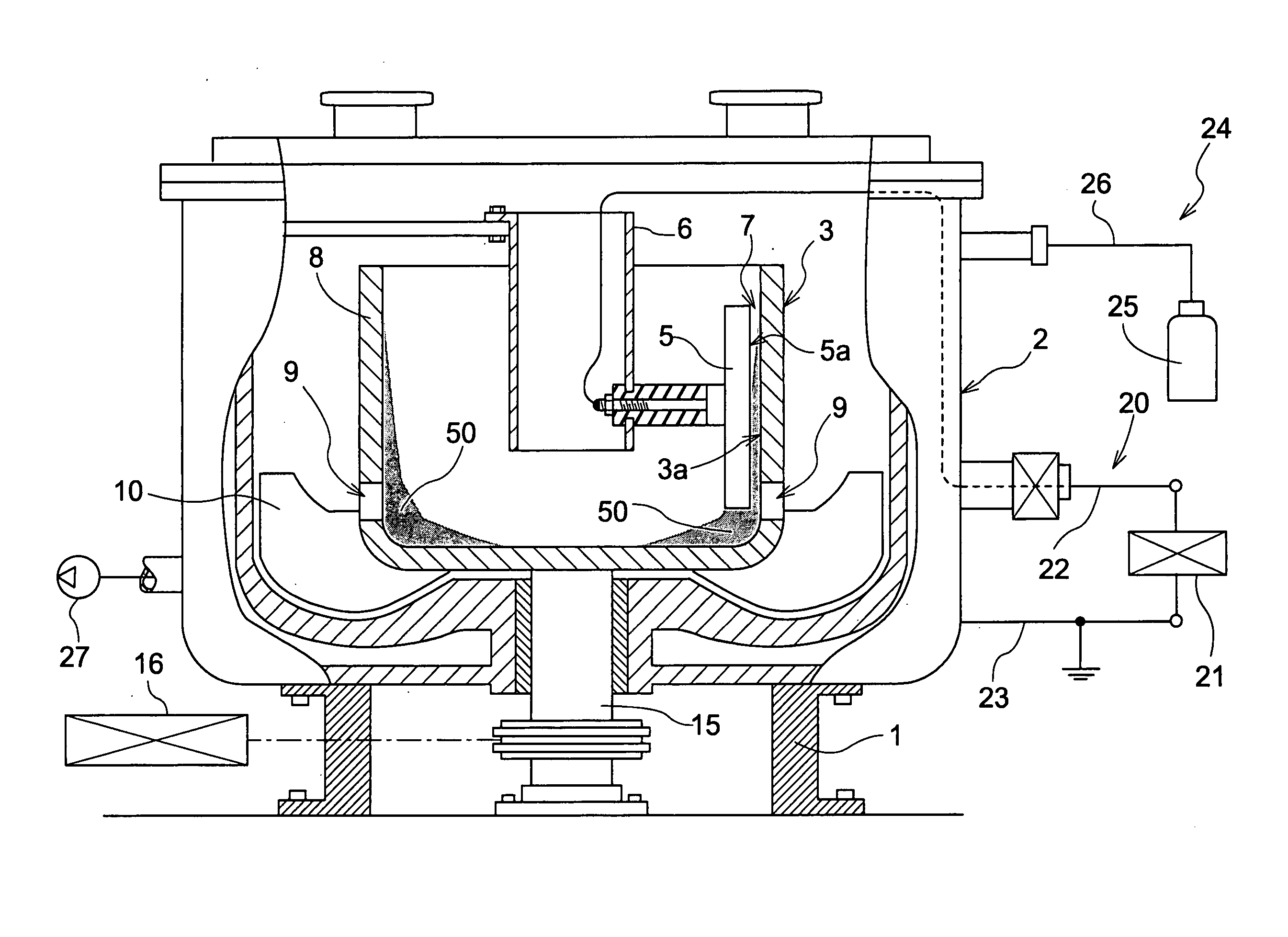
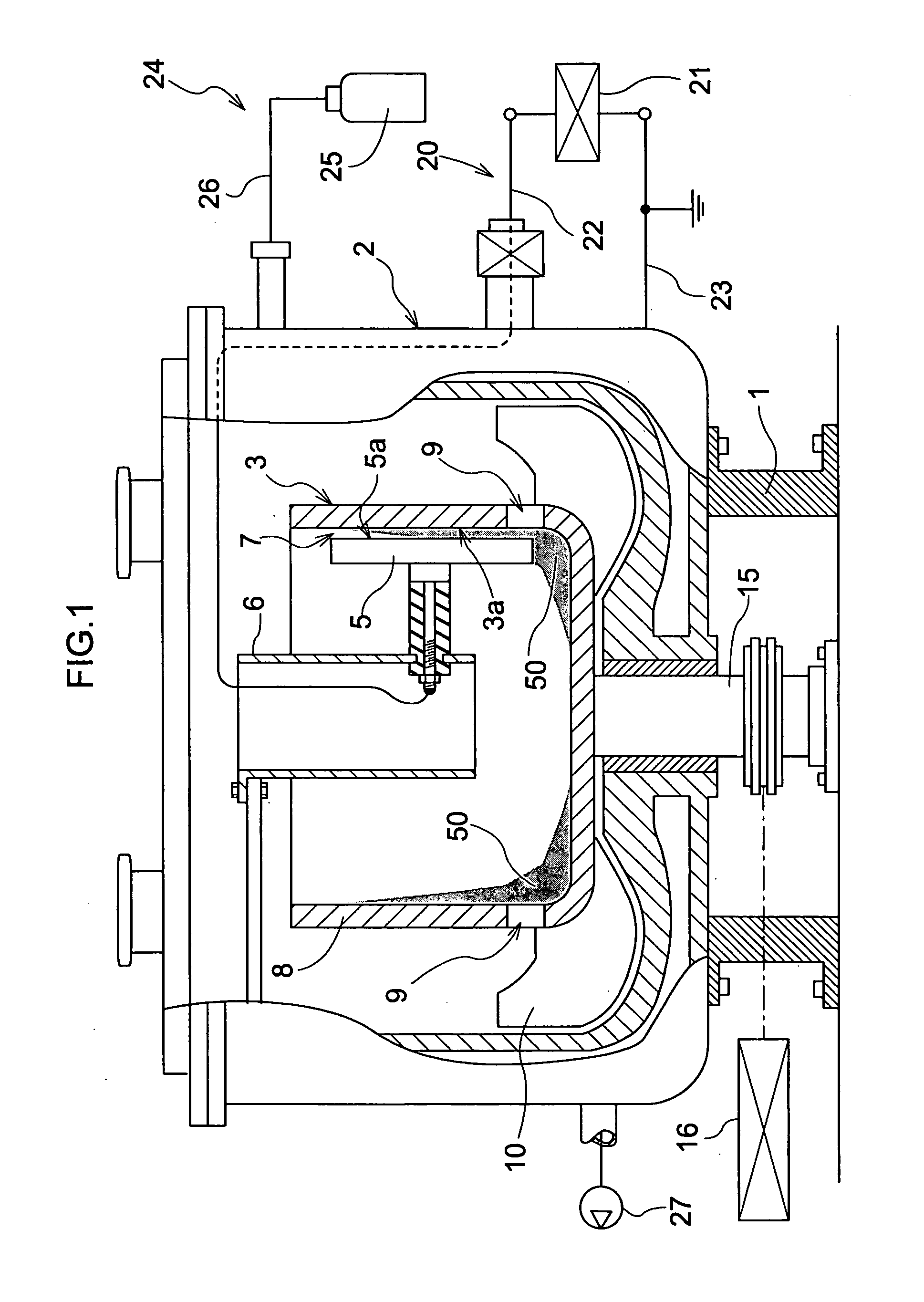
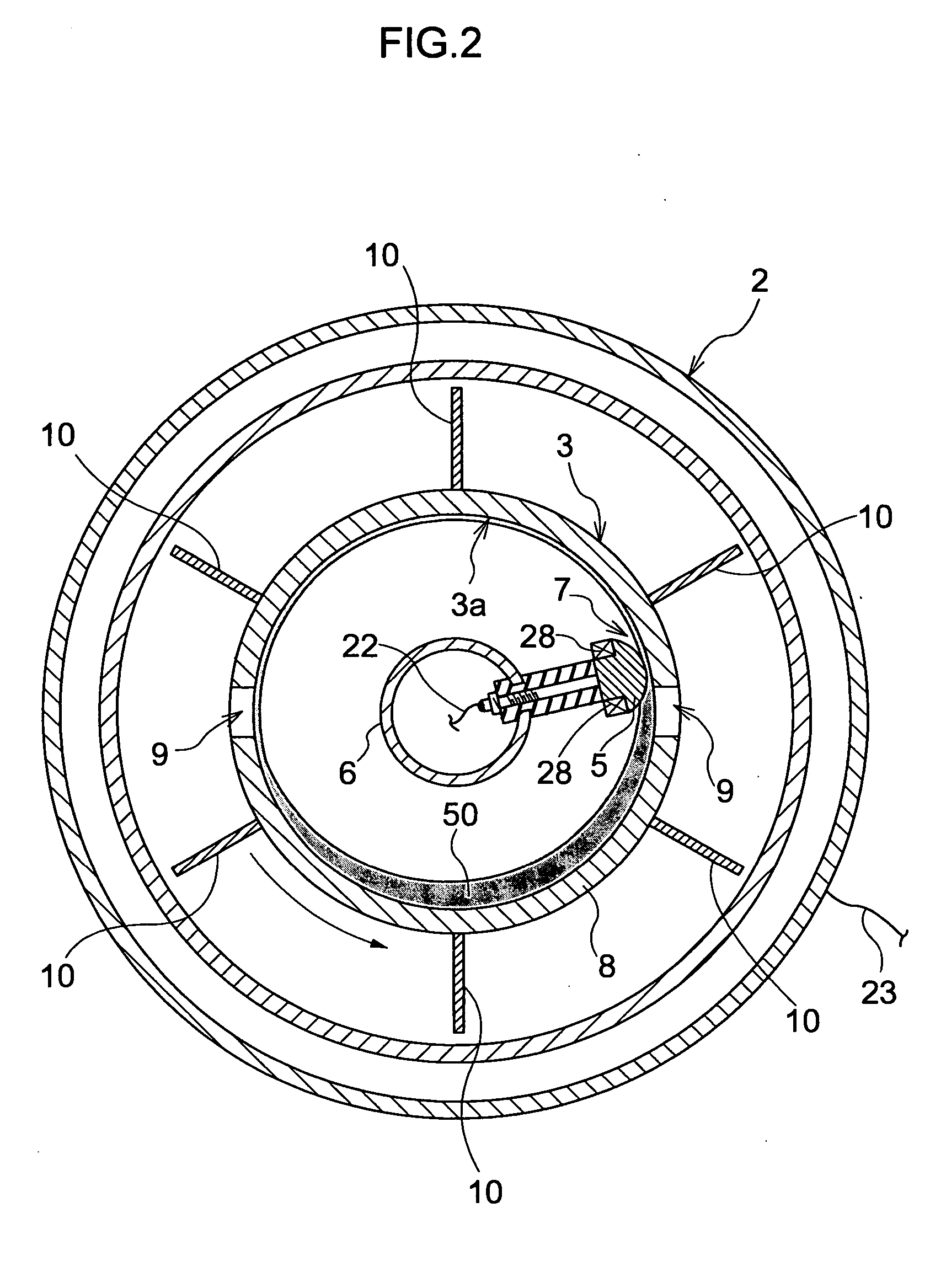
[0085] Next, there will be described a first embodiment of the powder processing apparatus relating to the present invention and suitable for implementing the above-described powder processing method with reference to FIG. 1 and FIG. 2.

[0086] A powder processing apparatus shown in FIG. 1 and FIG. 2 includes a substantially cylindrical casing 2 mounted on a base mount 1, a bottomed cylindrical container member 3 disposed inside this casing 2 and rotatable about a cylinder axis, and a press head 5 (an example of a processing member) disposed inside the container member 3 and fixed to the casing 2. The press head 5 projects from the side of the cylinder axis of the container member 3 toward an accumulating face 3a which is the inner face of the container member 3. And, at the leading end of the press head 5, there is formed a processing face 5a formed in opposition to the accumulating face 3a and convexly curved.

[0087] The container member 3 is fixed to ...

example 1

[0105] In this Example 1, nitrogen gas was supplied by the gas supplying means 24 into the casing 2 so as to fill the inside of the casing 2 with the nitrogen gas. Under this condition and for about 30 minutes, while milling treatment of the titanium oxide powder was effected at the gap 7 between the processing face 5a and the accumulating face 3a, glow discharge plasma was irradiated thereto, so as to compound nitrogen element in the nitrogen gas with the titanium oxide powder. By this method, yellow-colored nitrogen-containing titanium oxide powder can be manufactured.


PUM

PropertyMeasurementUnit
Diameteraaaaaaaaaa
Diameteraaaaaaaaaa
Temperatureaaaaaaaaaa

Abstract

In order to manufacture the compound powder or the porous granulated substance in an efficient manner, a powder processing apparatus has an accumulating face on which the processing target powder is to be accumulated and a processing face disposed in opposition to the accumulating face and convexly curved, and a moving means for moving the accumulating face and the processing face along the accumulating face relative to each other. The apparatus comprises an excitement treatment means capable of applying an excitation energy to the processing target powder accumulated on the accumulating face from an excitation energy supplying portion disposed in opposition to the accumulating face or an oscillation means for oscillating the accumulating face or the processing face in a direction intersecting the accumulating face.

Description

TECHNICAL FIELD [0001] The present invention relates to a powder processing method for milling processing target powder by applying, in particular, a compressive force and a shearing force thereto, as a mechanical treatment for activating the processing target powder by applying a mechanical force thereto. The present invention relates also to a powder processing apparatus having an accumulating face on which the processing target powder is to be accumulated and a processing face disposed in opposition to the accumulating face and convexly curved, and a moving means for moving the accumulating face and the processing face along the accumulating face relative to each other. The present invention relates also to a method of manufacturing porous granulated substance formed by coagulation of the processing target powder and having a number of pores. BACKGROUND ART [0002] Conventionally, as the powder processing apparatus of the above-noted type, there is known an apparatus having a bott...

Claims


Application Information

Patent Timeline
IPC IPC(8): B02C19/18B01J2/12B01J2/18B02C19/08B02C19/10B22F9/14
CPCB01J2/12B01J2/18B22F9/14B02C19/18B02C19/10B01J2/14Y10S241/14B02C15/08
Inventor NAITO, MAKIOABE, HIROYANOGI, KIYOSHIHOSOKAWA, MASUOFUKUI, TAKEHISAYOSHIKAWA, MASAHIRO
Owner HOSOKAWA MICRON CORP
Why Eureka
Try Eureka