Article incorporating a high temperature ceramic composite for selective emission

a ceramic composite and high temperature technology, applied in the field of ceramic composites, can solve the problems of low energy efficiency of incandescent lamps, loss of market share of compact fluorescent lamps, color, dimmability, acquisition cost,

Inactive Publication Date: 2007-10-04
GENERAL ELECTRIC CO
View PDF54 Cites 18 Cited by
  • Summary
  • Abstract
  • Description
  • Claims
  • Application Information

AI Technical Summary

Benefits of technology

[0008] In accordance with one aspect of the disclosure, an article is provided including a heating element and a high temperature coating coated on the heating element. The high temperature coating comprises a first region and a second region arranged in a structure such that the first and second regions maintain a periodicity of distribution between about 100 nm and about 1000 nm. Furthermore, the first region includes a first material selected from the group consisting of carbides of transition metals, nitrides of transition metals, and borides of transition metals.
[0009] In accordance with another aspect of the disclosure, another article is provided including a heating element and a high temperature coating coated on the heating element. The high temperature coating includes a first region and a second region arranged in a structure such that the first and second regions maintain a periodicity of distribution between about 100 nm and about 1000 nm. Furthermore, the first region includes a first material selected from the group consisting of carbides of transition metals, nitrides of transition metals, borides of transition metals and oxides of transition metals.

Problems solved by technology

Each of these devices has certain advantages and disadvantages depending upon the application within which they are to be used.
However, because much of the input energy of incandescent lamps is radiated outside the visible spectrum, incandescent lamps tend to have low energy efficiencies (e.g., on the order of 17 lumens per watt (LPW) for a 100 watt (100 W) lamp rated at 120 volts (120V) and having a rated lifetime of 750 hours).
Despite the many inherent advantages of incandescent lamps, if their efficiency cannot be improved, they will continue to lose market share to compact fluorescent lamps, which have an advantage in efficacy, albeit at the expense of color, dimmability, and acquisition cost.
However, all such suggested photonic crystal designs are limited by one or more factors including the materials and lattice structures employed, as well as the resulting efficiencies afforded.
This results in a band edge for the allowed band of energies occurring beyond 4 μm yielding a minimal increase in efficiency.
However, at such a small scale, 400 nm tungsten rods become extremely unstable when exposed to temperatures common to an incandescent environment (e.g., at or above 1700 Kelvin) for as little as two hours.
1(A-C) it can be easily seen that as the temperature is increased, the grain size within the rods increases toward the feature size causing the rods to become unstable.
Similarly, other mechanisms such as Raleigh instability may cause the logs to spheroidize into droplets rendering the structures unstable at high temperatures.
Thus, although the prior art may suggest methods of improving efficiencies of incandescent lamps, all such suggested improvements fail to teach material and structural combinations at the appropriate scale that are predicted to be stable at temperatures above 1700 Kelvin for extended periods of time.

Method used


Image

  • Article incorporating a high temperature ceramic composite for selective emission
  • Article incorporating a high temperature ceramic composite for selective emission
  • Article incorporating a high temperature ceramic composite for selective emission

Examples


example 1

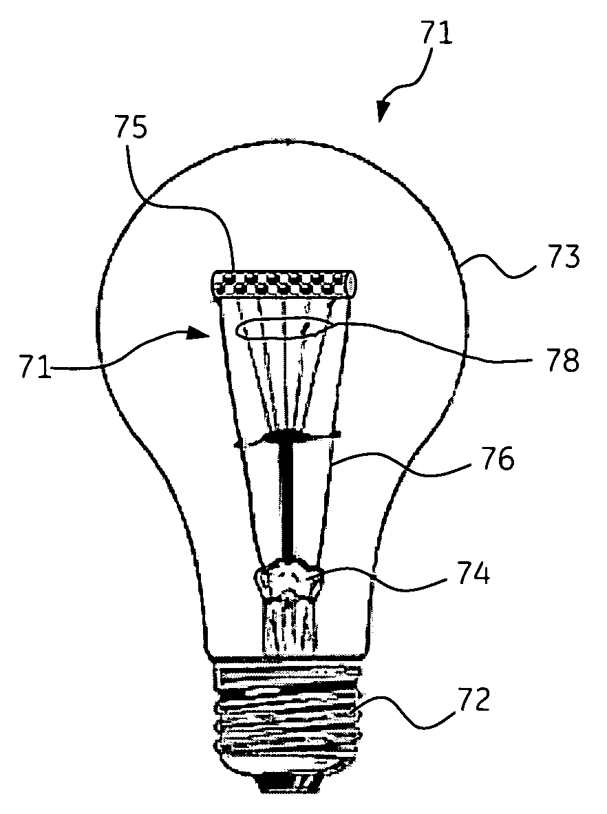
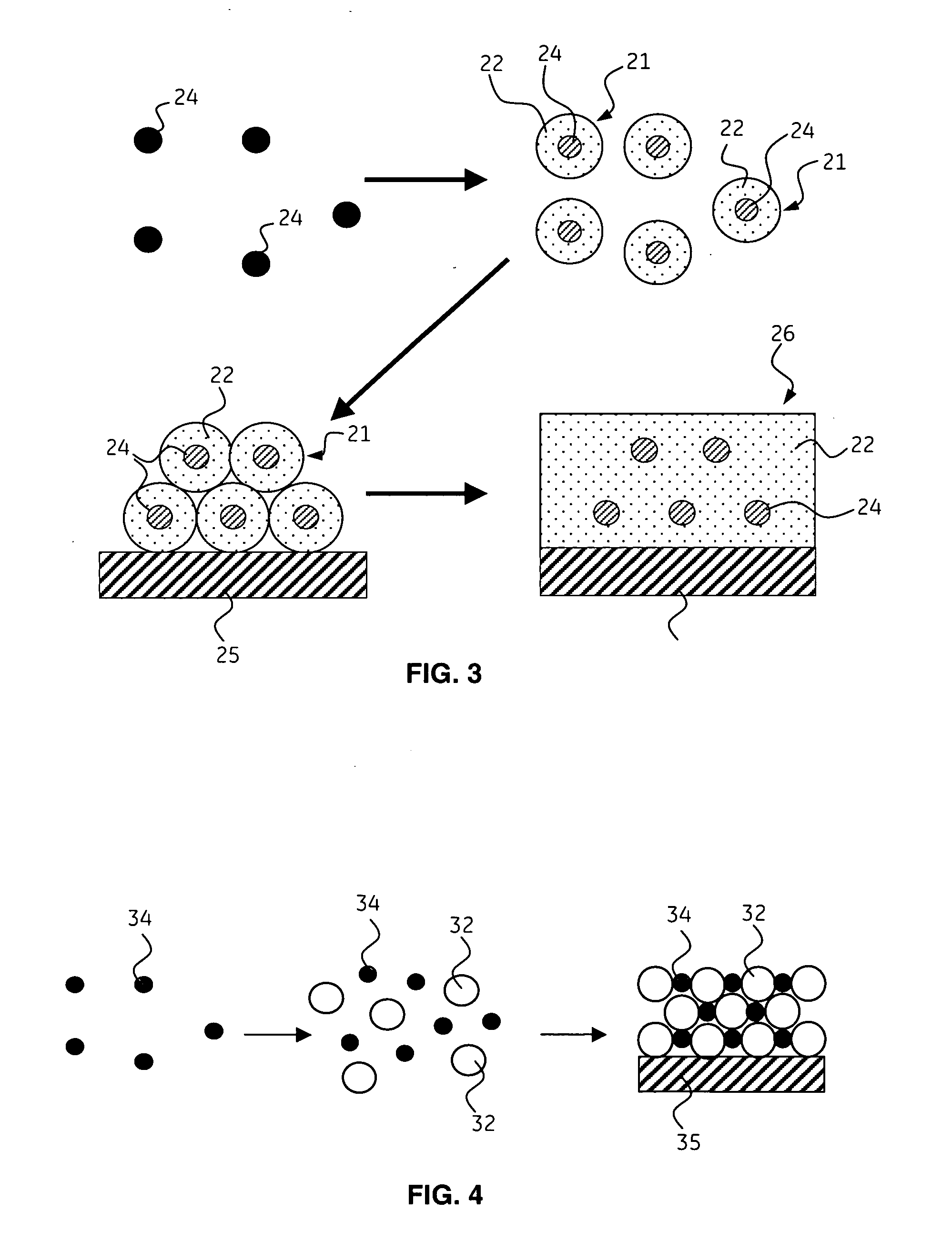
[0075] In one example, an incandescent lamp is made. The incandescent lamp includes a base, a heating element coated with a high temperature emissive ceramic composite and a light transmissive envelope attached to the base around the heating element. Before the heating element is mounted to the base, the ceramic composite is formed on the heating element. To form the ceramic composite, silica nanoparticles having a particle size of about 400 nm are assembled through electrophoresis or evaporation onto the heating element. Chemical vapor deposition (CVD) of silica is then used to bridge the silica nanoparticles to form an interconnected structure. A further CVD process is performed to infiltrate the silica matrix and form a 50 nm HfN ceramic shell around the silica nanoparticles. The silica particles are etched out with hydrofluoric acid. Because the HfN has a plasma frequency ωp such that ωp is greater than 8 eV indicating strong metallic behavior and the dielectric constant of the ...

example 2

[0076] In a second example, another incandescent lamp is made. The incandescent lamp includes a base, a tungsten filament coated with a high temperature emissive ceramic composite and a light transmissive envelope attached to the base around the tungsten filament. Before the tungsten filament is mounted to the base, the ceramic composite is formed on the filament. Composite nanoparticles consisting of a 150 nm tungsten core and a 100 nm coating of HfO2 are assembled on the filament using electrophoresis. The assembled particles are then sintered to form a monolithic coating on the tungsten filament. The coated filament is then mounted within the incandescent lamp and the envelope is attached and a fill gas comprising Ar and 10 ppm O2. Current is passed through the base to the ceramic coated filament causing the ceramic coating to selectively reflect photons having a wavelength greater than about 700 nm and to emit photons having a wavelength between about 400 nm and about 700 nm at ...


PUM

PropertyMeasurementUnit
wavelengthaaaaaaaaaa
temperaturesaaaaaaaaaa

Abstract

An article is provided including a heating element and a high temperature coating coated on the heating element. The high temperature coating comprises a first region and a second region arranged in a structure such that the first and second regions maintain a periodicity of distribution between about 100 nm and about 1000 nm. Furthermore, the first region includes a first material selected from the group consisting of carbides of transition metals, nitrides of transition metals, and borides of transition metals.

Description

BACKGROUND [0001] The presently claimed invention relates generally to a ceramic composite and related articles for selective emission of radiation. [0002] There are many classes and types of lighting devices available on the market today including incandescent lamps, discharge based lamps such as high intensity discharge (HID) and fluorescent lamps, as well as solid state devices such as Light Emitting Diodes (LEDs) and Organic LEDs (OLEDS). Each of these devices has certain advantages and disadvantages depending upon the application within which they are to be used. [0003] Tungsten filament incandescent lamps for example have numerous advantages for indoor and outdoor lighting systems. These advantages include simplicity of use, pleasing color, instant start, dimmability and low cost, not to mention a very large installation base. However, because much of the input energy of incandescent lamps is radiated outside the visible spectrum, incandescent lamps tend to have low energy eff...

Claims


Application Information

Patent Timeline
Patent Type & Authority Applications(United States)
IPC IPC(8): H01K1/14H01K1/50H01K1/02H01J1/15
CPCH01K1/04
Inventor SOMMERER, TIMOTHY JOHNMESCHTER, PETER JOELMIDHA, VIKASMINNEAR, WILLIAM PAULBRYAN, DAVID JEFFREY
Owner GENERAL ELECTRIC CO
Why Eureka
Try Eureka