Retrofit LED lamp for fluorescent fixtures without ballast

a technology of led lamps and fluorescent fixtures, which is applied in the field of retrofitting led lamps for fluorescent fixtures without ballast, can solve the problems of unreliable led lamps, unprotected led lamps, and high transient voltage spikes in any ac or dc system, and achieve the effects of increasing color, reducing labor costs, and increasing the number of colors

Active Publication Date: 2007-10-04
SIGNIFY HLDG BV
View PDF9 Cites 436 Cited by
  • Summary
  • Abstract
  • Description
  • Claims
  • Application Information

AI Technical Summary

Benefits of technology

[0139] Note that existing fluorescent lamps cannot be dimmed to 0% or they will simply go out, while LED lamps can be dimmed down to 0%. The bottom line is energy and cost saving. The cost savings comes into play, because the cost of dimmable fluorescent ballasts is usually more than twice the cost of a standard non-dimmable fluorescent ballast, and these dimmable ballasts require a special dimming switch at an additional cost. In addition, savings in lower electrical bills can be significant.
[0140] Another circuit module can be a color effects module for use with color LEDs instead of white LEDs used in the LED lamps. This module allows the LED lamp to change col

Problems solved by technology

There can be high transient voltage spikes in any AC or DC system.
However, without them, the LED lamps become unreliable and not protected from external voltage spikes that may permanently damage the internal electronic components within the LED lamp.
In addition, the cost involved for the labor to retrofit and re-wire all the existing fluorescent lighting in a commercial or industrial building can be quite expensive.
When Nichia Corporation first introduced the first white LED back in 1996; there were some problems with the new technology.
Some of these obstacles included wide manufacturing tolerances for color temperature and intensity, low light output per unit, low efficacy (under 15 to 24 lumens per watt (LPW)), poor lumen maintenance, and lastly, high expense.
These drawbacks prevented wide acceptance, promotion, sale, and implementation of LED lamps in the beginning.
When incorporated into a system, they can exceed the efficacy of fluorescent lighting.
Obviously, the final cost for a similar tubular LED linear lamp will vary depending on the type and quantity of LEDs used.
A line voltage version of a fluorescent lamp is not applicable.
Daylight harvesting is beneficial from two standpoints: sunlight is good for people, and electricity is expensive, both financially and environmentally.
The financial costs of not turning off or dimming electric lights include unnecessarily high electric bills for lighting and for the air conditioning required to remove heat created by lights.
But the total costs go far beyond economics to include eyestrain, because of excessive brightness and even a lessening of emotional and intellectual well-being.
Unlike incandescent lamps, fluorescent lamps cannot be directly connected to alternating current power lines.
Unless the flow of current is somehow stabilized, more and more current will flow through the lamp until it overheats and eventually destroys itself.
Unfortunately, the additive approach does not reduce or eliminate the amount of hazardous mercury in the environment.
More importantly, the additives may not work as effectively in the

Method used


Image

  • Retrofit LED lamp for fluorescent fixtures without ballast
  • Retrofit LED lamp for fluorescent fixtures without ballast
  • Retrofit LED lamp for fluorescent fixtures without ballast

Examples


Embodiment Construction

[0335] It is noted that the immediate following disclosure relates to continuation-in-part application Ser. No. 11 / 198,633, the parent application of the present application. The disclosure of the present child application begins with FIG. 87 and continues through to FIG. 97.

[0336] Reference is now made to the drawings and in particular to FIGS. 1-97 in which identical of similar parts are designated by the same reference numerals throughout.

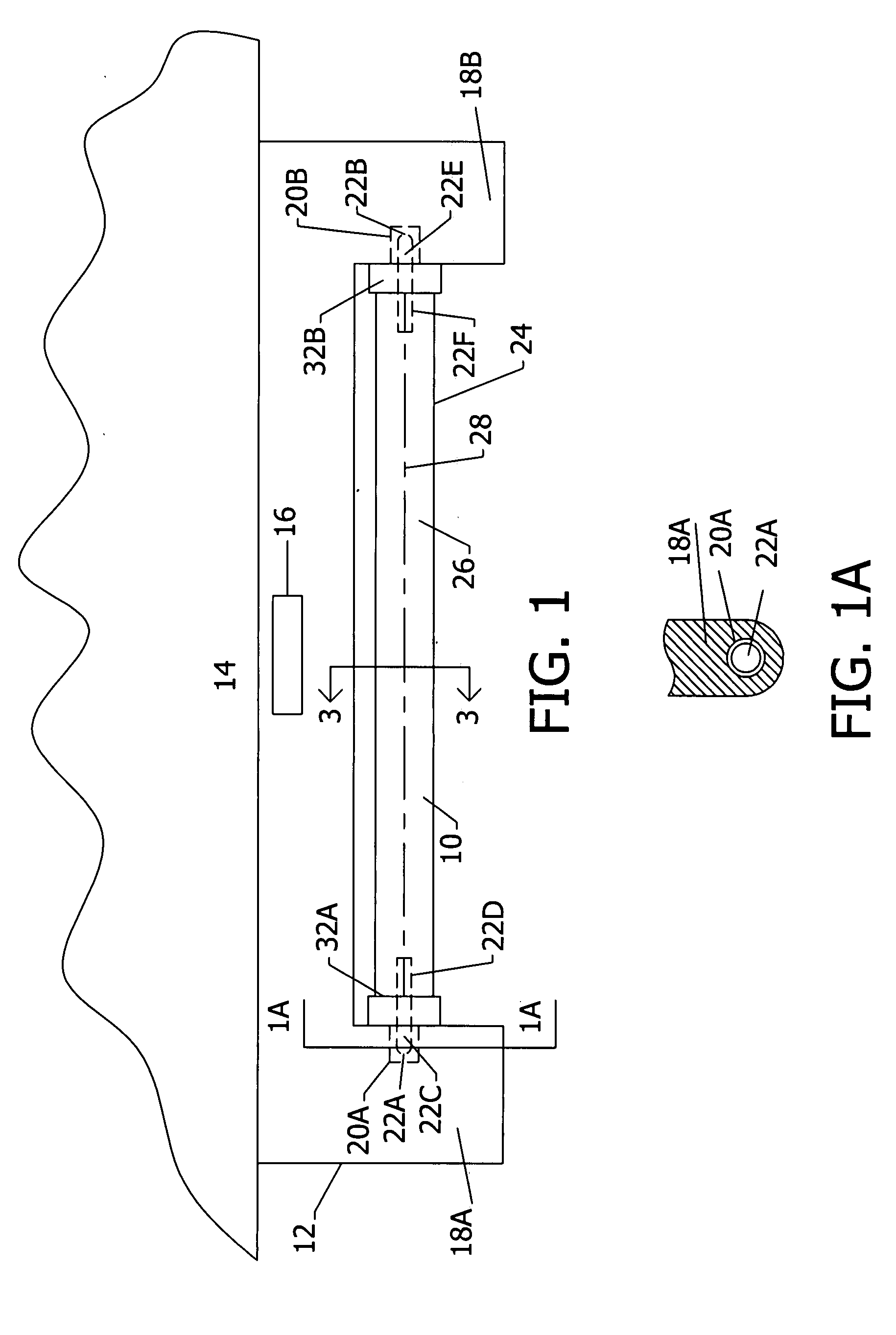
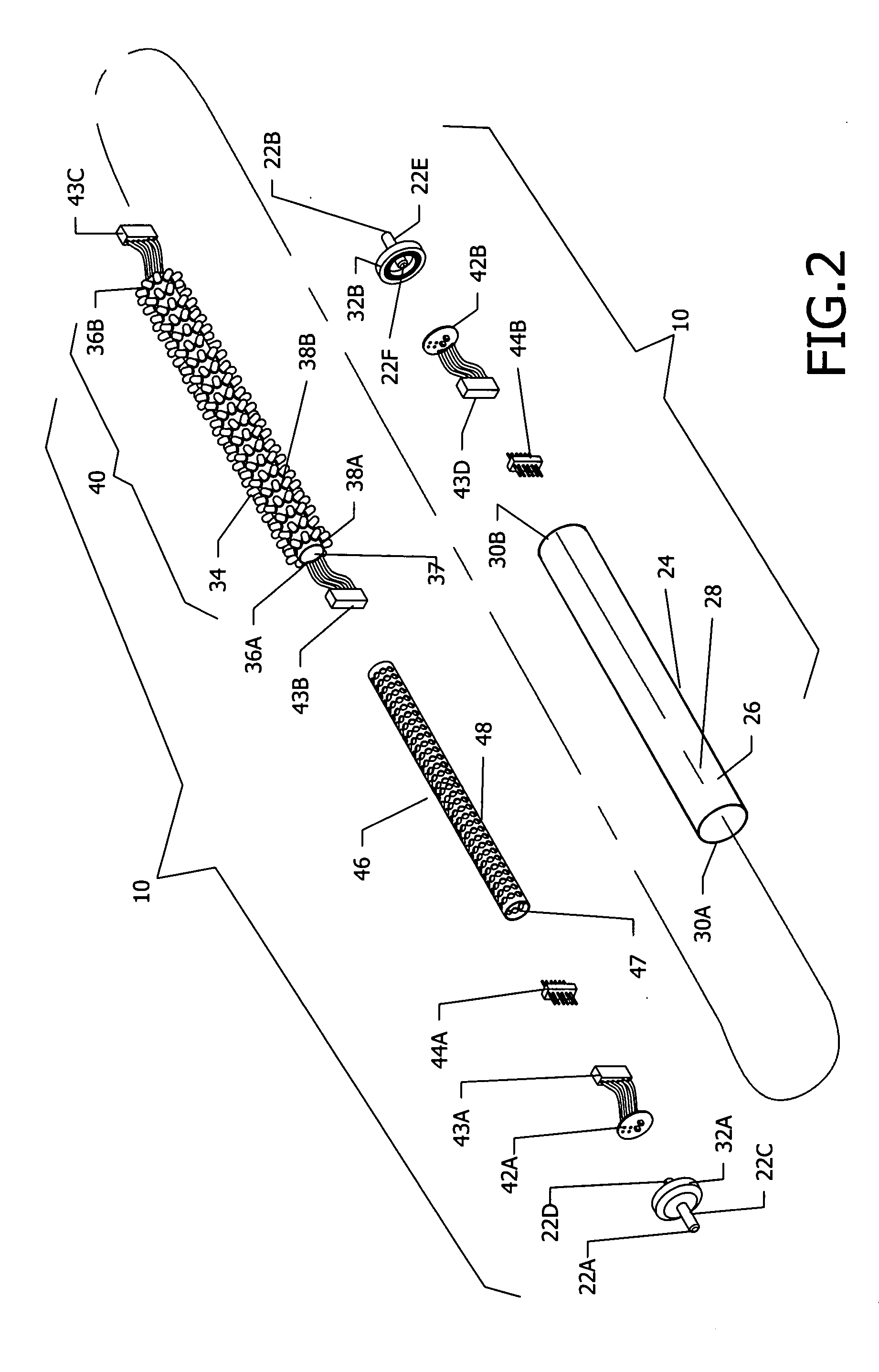
[0337] An LED lamp 10 shown in FIGS. 1-10 is seen in FIG. 1 retrofitted to an existing elongated fluorescent fixture 12 mounted to a ceiling 14. An instant start type ballast assembly 16 is positioned within the upper portion of fixture 12. Fixture 12 further includes a pair of fixture mounting portions 18A and 18B extending downwardly from the ends of fixture 12 that include ballast electrical contacts shown as ballast end sockets 20A and 20B that are in electrical contact with ballast assembly 16. Fixture sockets 20A and 20B are each single ...


PUM


Abstract

An energy saving device for an LED lamp mounted to an existing fixture for a fluorescent lamp where the ballast is removed or bypassed. The LEDs are positioned within a tube and electrical power is delivered from a power source to the LEDs. The LED lamp includes means for controlling the delivery of the electrical power from the power source to the LEDs, wherein the use of electrical power can be reduced or eliminated automatically during periods of non-use. Such means for controlling includes means for detecting the level of daylight in the illumination area of said least one LED, in particular a light level photosensor, and means for transmitting to the means for controlling relating to the detected level of daylight from the photosensor. The photosensor can be used in operative association with an on-off switch in power connection to the LEDs, a timer, or with a computer or logic gate array in operative association with a switch, timer, or dimmer that regulates the power to the LEDs. An occupancy sensor that detects motion or a person in the illumination area of the LEDs can be also be used in association with the photosensor and the computer, switch, timer, or dimmer, or in solo operation by itself. Two or more such LED lamps with a computer or logic gate array used with at least one of the lamps can be in network communication with at least one photosensor and/or at least one occupancy sensor to control the power to all the LEDs.

Description

HISTORY OF THE INVENTION [0001] This application is a continuation-in-part of U.S. application Ser. No. 11 / 198,633, filed on Aug. 5, 2005, which is a continuation-in-part of U.S. Pat. No. 7,067,992, issued on Jun. 27, 2006, which is a continuation-in-part of U.S. Pat. No. 6,853,151, issued on Feb. 8, 2005, which is a continuation-in-part of U.S. Pat. No. 6,762,562, issued on Jul. 13, 2004.FIELD OF THE INVENTION [0002] The present invention relates to a fluorescent replacement LED lamp powered directly by a power source with power control devices. BACKGROUND OF THE INVENTION [0003] U.S. Pat. Nos. 6,762,562; 6,853,151; 7,067,992; and U.S. patent application Ser. No. 11 / 198,633 set forth LED arrays positioned in tubes that are powered by reduced voltage from a ballast. This reduced voltage can be provided with various controls positioned inside or outside of the tubes, so that the illumination from the LED arrays can be varied, or switched to an on or off mode in accordance with illumi...

Claims


Application Information

Patent Timeline
IPC IPC(8): H05B37/02
CPCF21K9/17F21Y2101/02H05B33/0803Y02B20/386H05B33/0851H05B33/0854H05B33/0809Y10S362/80Y10S362/802F21Y2115/10F21K9/278H05B45/10H05B45/37Y02B20/30H05B45/3578H05B45/12
Inventor KIT, JOHN
Owner SIGNIFY HLDG BV
Why Eureka
Try Eureka