Dielectric Resonance Apparatus, Oscillation Apparatus, and Transmission/Reception Apparatus

a technology of dielectric resonance and oscillation apparatus, which is applied in the direction of oscillator, waveguide, resonator, etc., can solve the problems of increasing the area of the dielectric substrate, increasing the cost, and large area of the dielectric resonance apparatus, so as to reduce the production cost and stable electric characteristics

Active Publication Date: 2007-10-04
MURATA MFG CO LTD
View PDF4 Cites 7 Cited by
  • Summary
  • Abstract
  • Description
  • Claims
  • Application Information

AI Technical Summary

Benefits of technology

[0012] Accordingly, it is an object of the present invention to provide a dielectric resonance apparatus, an oscillation apparatus, an...

Problems solved by technology

Furthermore, since the power-supply lines are arranged outside of the resonator, the area of the dielectric resonance apparatus also tends to be large.
Since the dielectric substrate used for the dielectric resonator block has a high dielectric constant, the cost tends to be increased, and furthermore, the area of the dielectric substrate tends to be increased.
This leads to the problem that t...

Method used


Image

  • Dielectric Resonance Apparatus, Oscillation Apparatus, and Transmission/Reception Apparatus
  • Dielectric Resonance Apparatus, Oscillation Apparatus, and Transmission/Reception Apparatus
  • Dielectric Resonance Apparatus, Oscillation Apparatus, and Transmission/Reception Apparatus

Examples


first embodiment

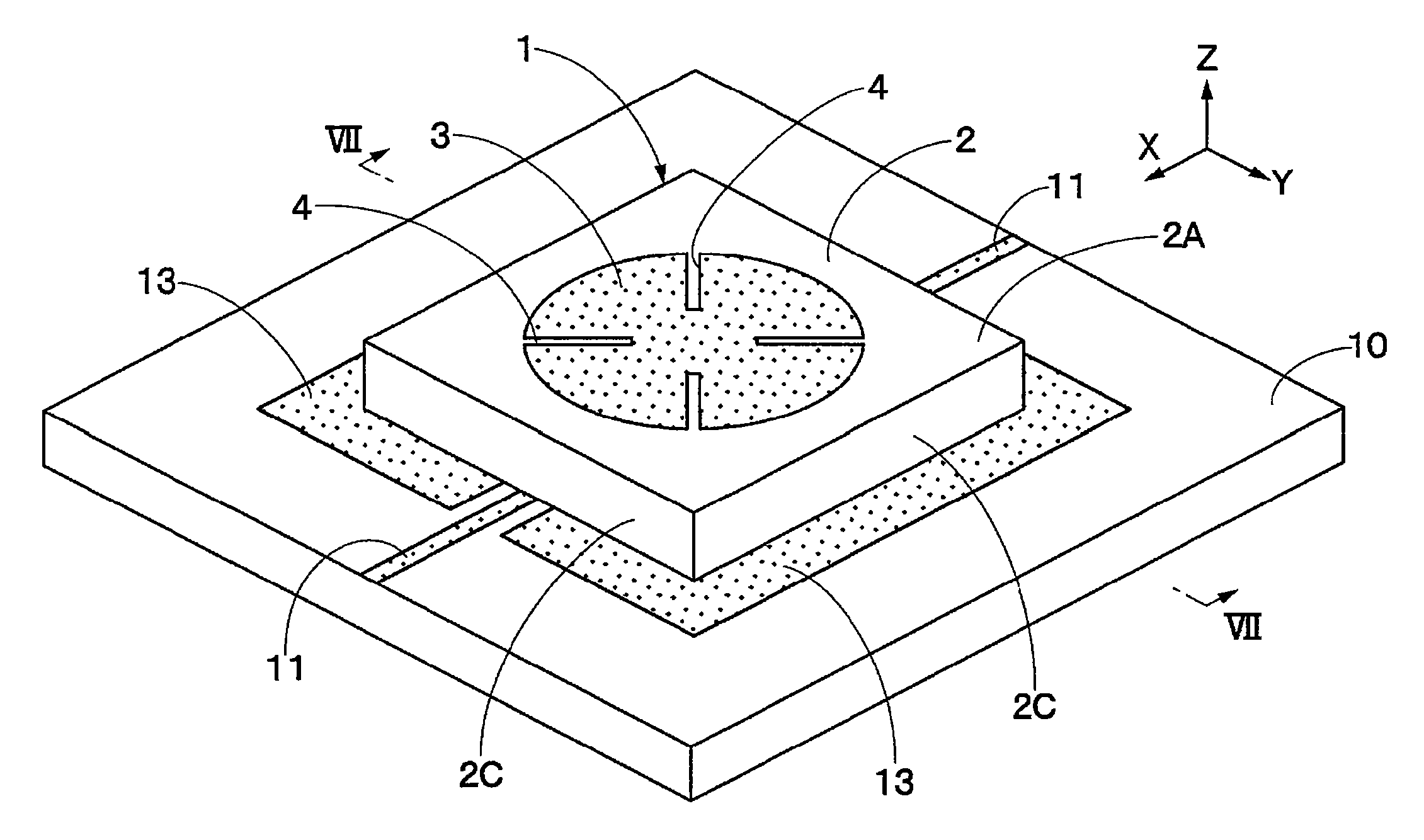
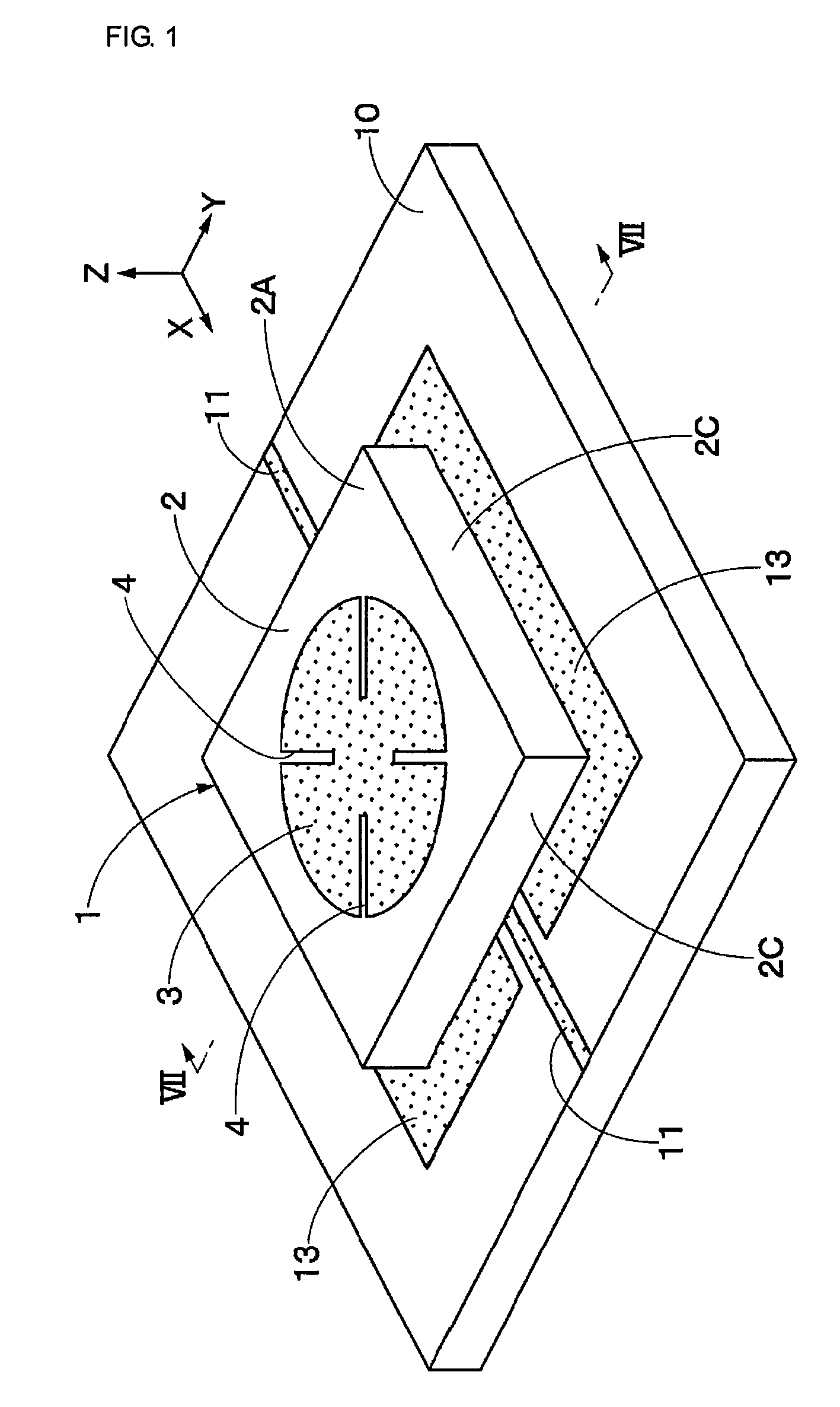
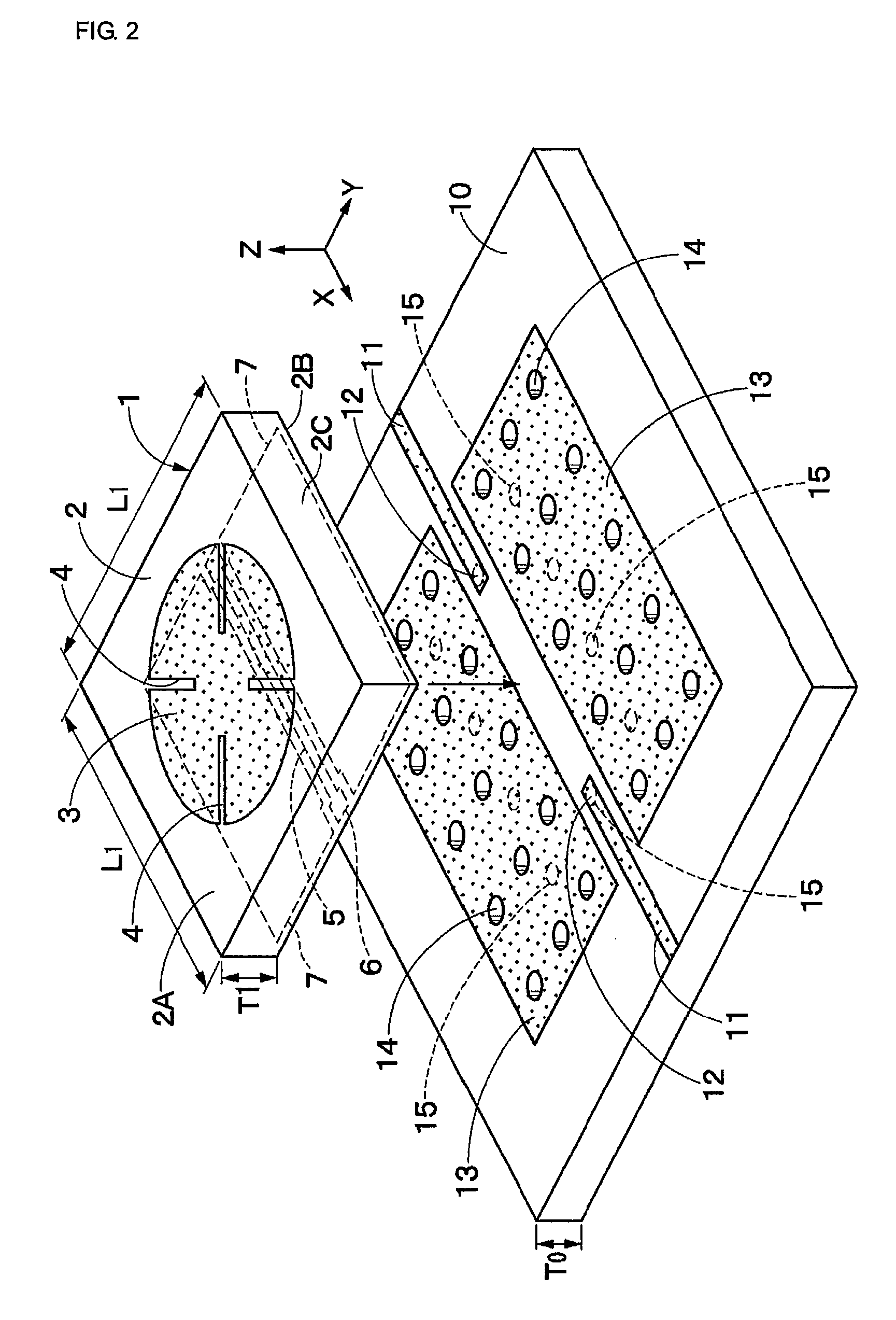
[0085] Referring to FIGS. 1 to 8 which show a dielectric resonance apparatus a TM010-mode resonator 1 includes a dielectric substrate 2, a substantially circular electrode 3, and a back-surface electrode 7, which will be described later.

[0086] The dielectric substrate 2 has a plate shape (a chip shape) and is made of a dielectric material. An example of the dielectric material used for the dielectric substrate 2 is a ceramic material having a relative dielectric constant ∈r1 of approximately 26 (for example, ∈r=26). The dielectric substrate 2 is a substantially square plate having sides of length L1 in the X direction (vertical direction) and Y direction (horizontal direction) and having a thickness T1 in the Z direction (thickness direction).

[0087] The substantially circular electrode 3 is disposed on a surface 2A of the dielectric substrate 2. The substantially circular electrode 3 is made of a thin film using a metal material, for example, and disposed in a center of the dielec...

second embodiment

[0138] In the second embodiment, the gap widths δ3 included in the open portions 28 are uniform in all of the coupling electrodes 27. However, the present invention is not limited to this, and as a third modification shown in FIG. 18, the gap width of the open portions 28 may be designed so as to be large only around the short-circuit points S1, and therefore, large-width portions 28A may be designed at tips of the open portions 28. In this case, an amount of coupling is set in accordance with the gap width of each of the large-width portions.

[0139] In the second embodiment, the amount of coupling between the coupling electrodes 27 and the TM010-mode resonator 21 is set to a desired amount in accordance with the gap width δ3 included in each of the open portions 28. However, the present invention is not limited to this. The amount of coupling between the coupling electrodes 27 and the TM010-mode resonator 21 may be set to a desired amount in accordance with the distance between a po...

third embodiment

[0145] Referring to FIGS. 23 to 26, an oscillation apparatus according to the present invention will now be described. In this embodiment, two back-surface electrodes are arranged on either side of the coupling line serving as a magnetic-field coupling section and are arranged on a back surface of the dielectric substrate of the TM010-mode resonator. Furthermore, one of the back-surface electrodes has a coupling electrode which has a short-circuit point surrounded by an opening portion and which serves as another magnetic-field coupling section, and the oscillation apparatus is configured using a TM010-mode resonator.

[0146] An oscillation circuit substrate 31 serving as an external substrate is made of an dielectric material. An oscillation circuit unit 32 and a frequency control circuit unit 40, which will be described later, are arranged on the oscillation circuit substrate 31 serving as an external substrate, and furthermore, a TM010-mode resonator 43 is implemented on a surface ...


PUM


Abstract

A substantially circular electrode 3 is arranged on a surface 2A of a dielectric substrate 2 of a TM010-mode resonator 1. A coupling line 5, which extends along a diameter of the substantially circular electrode 3, is arranged on a back surface 2B of the dielectric substrate 2, and back-surface electrodes 7 are arranged with the coupling line 5 interposed therebetween in the width direction. Furthermore, signal lines 11 and ground electrodes 13 are arranged on a surface of an external substrate 10 in positions other than portions facing the coupling line 5 of the TM010-mode resonator 1. The signal lines 11 are connected to the coupling line 5 of the TM010-mode resonator 1 and the ground electrodes 13 is connected to the back surface electrodes 7.

Description

[0001] This is a continuation of application Ser. No. PCT / JP2005 / 023578, filed Dec. 22, 2005. TECHNICAL FIELD [0002] The present invention relates to dielectric resonance apparatuses which oscillate high-frequency electro-magnetic waves such as microwaves and millimeter waves, oscillation apparatuses using the dielectric resonance apparatuses, and transmission / reception apparatuses. BACKGROUND ART [0003] In general, a known dielectric resonance apparatus includes a resonator having a circular electrode on a surface of a dielectric substrate and power-supply lines which are arranged on the dielectric substrate and which are arranged in the vicinity of ends of the resonator (see, for example, Patent Document 1). [0004] Furthermore, a known oscillation apparatus using a dielectric resonance apparatus includes an oscillator block which oscillates signals having predetermined oscillation frequencies and a dielectric resonator block constituted by a TM010-mode resonator used for setting t...

Claims


Application Information

Patent Timeline
IPC IPC(8): H01P7/08H01P7/10
CPCH01P7/082H03B5/1876H01P7/10
Inventor OKANO, TAKESHI
Owner MURATA MFG CO LTD
Why Eureka
Try Eureka