
Multilayer ceramic electronic device and method of production of same

a technology of electronic devices and ceramics, applied in the direction of capacitor manufacture, fixed capacitors, electrical equipment, etc., can solve the problems of multilayer ceramic capacitors suffering from structural defects, multilayer ceramic capacitors becoming weak in mechanical strength, and prone to loss of dielectric properties of dielectric layers, so as to prevent the formation of structural defects such as cracks, the effect of preventing the formation of cracks

Inactive Publication Date: 2007-10-04
TDK CORPARATION
View PDF6 Cites 10 Cited by
  • Summary
  • Abstract
  • Description
  • Claims
  • Application Information

AI Technical Summary

Benefits of technology

[0012]The present invention was made in consideration of this actual situation and has as its object to provide a method of production of a multilayer ceramic electronic device able to prevent the multilayer ceramic electronic device from dropping in mechanical strength and from causing structural defects such as cracks at a low cost even if annealing the sintered body for reoxidation and such a multilayer ceramic electronic device.
[0014]By making the dew point of the annealing atmosphere gas in the reoxidation step −50 to 0° C. and making the temperature of the annealing atmosphere gas in the reoxidation step 900 to 1100° C., it is possible to control the oxygen partial pressure in the annealing atmosphere gas to within a predetermined range. By annealing the sintered body in the range of this oxygen partial pressure for reoxidation, it is possible to prevent the multilayer ceramic capacitor from dropping in mechanical strength and causing structural defects such as cracks. Further, as control of the dew point and temperature of the annealing atmosphere gas is simple, compared with annealing under a high pressure atmosphere, it is possible to prevent the multilayer ceramic capacitor from dropping in mechanical strength and causing structural defects such as cracks by a lower cost.
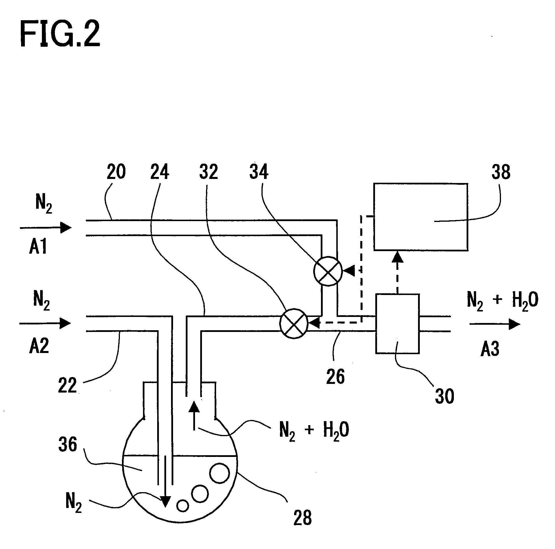
[0016]By adjusting the ratio of mixture of N2 and H2O in the annealing atmosphere gas, it is possible to easily control the oxygen partial pressure in the annealing atmosphere gas. As a result, compared with annealing under a high pressure atmosphere, it is possible to prevent the multilayer ceramic capacitor from dropping in mechanical strength at a low cost and possible to prevent structural defects such as cracks.
[0019]By making the amount of Si existing at the outer layer side 0.5 to less than 2 times the amount of Si existing at the inner side, it is possible to improve the multilayer ceramic electronic device in mechanical strength and prevent structural defects such as cracks.
[0021]When using Ni or another inexpensive base metal for the internal electrode layers, to metallize the internal electrode layers without causing oxidation, the green chip is fired in a reducing atmosphere. When annealing to reoxidize the dielectric layers reduced by this firing, it is possible to prevent the multilayer ceramic capacitor from dropping in mechanical strength and structural defects such as cracks from being formed at a low cost by controlling the dew point and temperature of the annealing atmosphere gas within the above ranges.

Problems solved by technology

However, if firing a green chip in a reducing atmosphere, the dielectric layers are reduced to be converted into a semiconductor, and the dielectric property of the dielectric layer is liable to be lost.
However, in conventional annealing, the annealing atmosphere gas cannot be suitably controlled in oxygen partial pressure and temperature, the multilayer ceramic capacitor becomes weak in mechanical strength, and the multilayer ceramic capacitor suffers from structural defects such as cracks.
As a result, the base metal in the internal electrode layers ends up oxidizing.
The oxidation of the base metal in the internal electrode layers causes the internal electrode layers to expand in volume to result in reducing mechanical strength of the multilayer ceramic capacitor and forming cracks.
Conversely, if the annealing atmosphere gas is too low in oxygen partial pressure, the dielectric layers are liable to be insufficiently reoxidized.
Further, if the annealing atmosphere gas is too high in temperature, the dielectric layers are reoxidized well, but the internal electrode layers as well end up being oxidized and cracks are liable to occur.
Conversely, if the annealing atmosphere gas is too low in temperature, the dielectric layers are liable to be insufficiently reoxidized.
However, raising the firing temperature may cause problems of a change in the IR life or temperature characteristic of the capacitor.
However, in this method, expensive facilities are necessary for annealing under a high pressure of 100 to 1000 atmospheres.

Method used


Image

  • Multilayer ceramic electronic device and method of production of same
  • Multilayer ceramic electronic device and method of production of same
  • Multilayer ceramic electronic device and method of production of same

Examples


example 1

[0102](Preparation of Green Sheet)

[0103]As shown below, the main ingredient materials and the sub ingredient materials were wet mixed in a predetermined molar ratio by a ball mill for 16 hours, then dried to obtain a dielectric material. Note that the main ingredient materials and the sub ingredient materials had particle sizes of 0.1 to 1.0 μm. BaTiO3: 100 mol %, MgCO3: 3.0 mol %, MnCO3: 0.5 mol %, (Ba0.6Ca0.4)SiO3: 3.0 mol %, Y2O3: 5.0 mol %.

[0104]Note that the above-mentioned 3.0 mol % of (Ba0.6Ca0.4)SiO3 was wet mixed with 1.8 mol % of BaCO3, 1.2 mol % of CaCO3, and 3 mol % of SiO2 by a ball mill for 16 hours, then dried and fired at 1150° C. in the air, then further wet pulverized by a ball mill for 100 hours.

[0105]Next, the obtained dielectric material was mixed and dispersed with a solvent, dispersant, plasticizer, and organic vehicle in a predetermined ratio, then converted to a paste to obtain a dielectric layer paste.

[0106]Next, the obtained dielectric layer paste was used...


PUM

PropertyMeasurementUnit
Temperatureaaaaaaaaaa

Abstract

An object of the present invention is to provide a method of production of a multilayer ceramic electronic device able to prevent the multilayer ceramic electronic device from dropping in mechanical strength and causing structural defects such as cracks at a low cost even if annealing the sintered body for reoxidation, and also such a multilayer ceramic electronic device, i.e., a method of production of a multilayer ceramic electronic device including a step of stacking green sheets and internal electrode layers to obtain a green chip, a step of firing the green chip under a reducing atmosphere to obtain a sintered body, and a reoxidation step of annealing the sintered body in a predetermined annealing atmosphere gas, wherein the annealing atmosphere gas in the reoxidation step has a dew point of −50 to 0° C., and the annealing atmosphere gas in the reoxidation step has a temperature of 900 to 1100° C.

Description

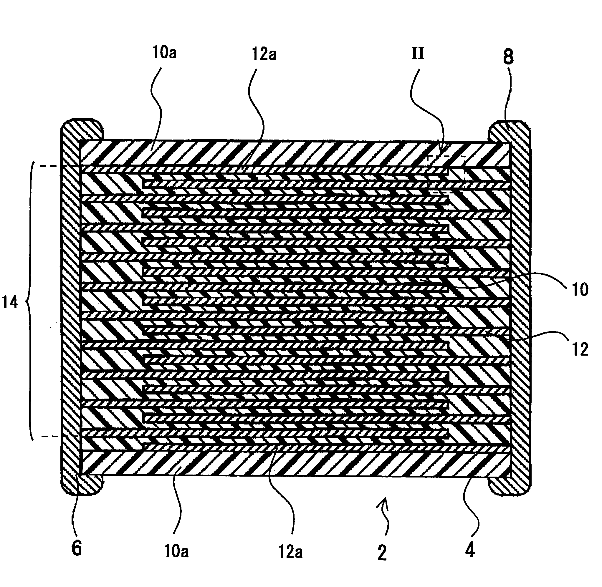
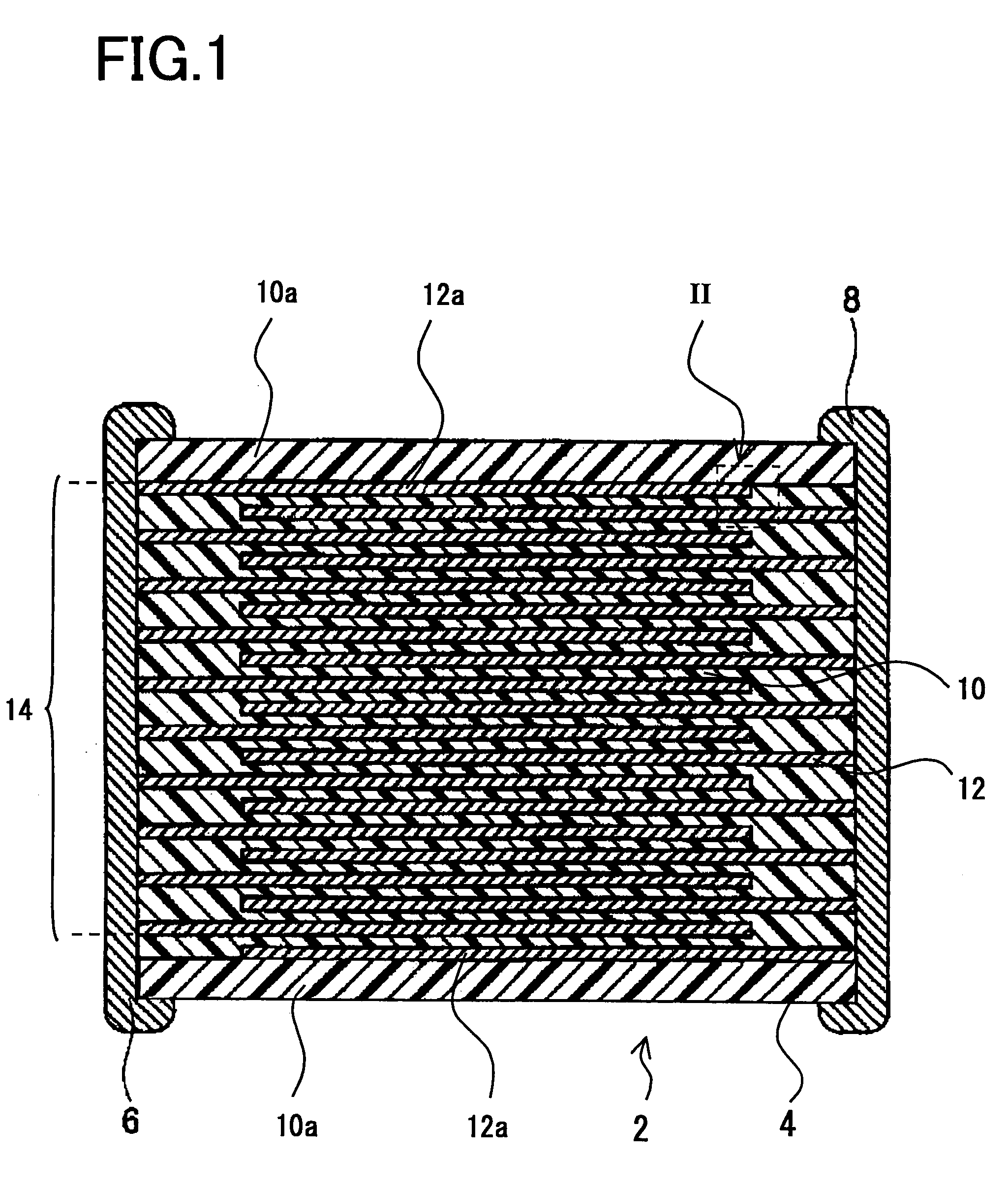
BACKGROUND OF THE INVENTION[0001]1. Field of the Invention[0002]The present invention relates to a method of production of a multilayer ceramic electronic device such as multilayer ceramic capacitor and a multilayer ceramic electronic device.[0003]2. Description of the Related Art[0004]A multilayer ceramic capacitor, one example of a multilayer ceramic electronic device, is comprised of a capacitor device body configured by dielectric layers comprised of a dielectric ceramic composition of a predetermined composition and internal electrode layers having various metals as main ingredients alternately stacked. This type of multilayer ceramic capacitor is usually formed by printing an internal electrode paste on a ceramic green sheet comprised of a dielectric ceramic composition, stacking a plurality of green sheets on which internal electrode paste has been printed, cutting the stack of the ceramic green sheets into predetermined dimensions to obtain a ceramic green chip, treating it ...

Claims


Application Information

Patent Timeline
IPC IPC(8): H01G4/06H01G4/12H01G4/30H01G13/00
CPCB32B18/00H01G4/30C04B35/638C04B2235/3206C04B2235/3208C04B2235/3225C04B2235/3262C04B2235/3418C04B2235/3436C04B2235/3454C04B2235/5445C04B2235/6025C04B2235/656C04B2235/6562C04B2235/6565C04B2235/6582C04B2235/6584C04B2235/6588C04B2235/663C04B2235/96C04B2237/704H01G4/0085H01G4/12C04B35/4682
Inventor FUJIMURA, TOMOYOSHISATO, AKIRA
Owner TDK CORPARATION
Learn More