Illumination systems

a technology of illumination system and fluorescent light tube, which is applied in the direction of continuous variable inductance/transformer, electric variable regulation, inductance, etc., can solve the problems of consuming a relatively large amount of electrical power, fluorescent light source a relatively short life of approximately 20,000 hours, and fluorescent light source is usually quite fragile, so as to improve reliability, reduce cost, and improve efficiency

Inactive Publication Date: 2007-10-11
EMD TECH
View PDF42 Cites 96 Cited by
  • Summary
  • Abstract
  • Description
  • Claims
  • Application Information

AI Technical Summary

Benefits of technology

[0021]According to yet another embodiment, in an illumination system, an installation method is used for contactless coupling one or several illumination modules to a power supply. The illumination system comprises a master power supply constructed and arranged to provide electrical power to a primary wire forming a current loop; and an illumination module including an electromagnetic coupling element and several light sources. The electromagnetic coupling element includes a magnetic core. The method includes positioning one or several of the illumination modules constructed to provide light; and positioning the primary wire in a close proximity to the illumination module without establishing an electrical connection, the positioning enabling inductive power transfer from the primary wire to a secondary wire wound around at least a portion of the ferromagnetic core, wherein the secondary wire is connected to provide current to one or multiple li

Problems solved by technology

However, fluorescent light sources have a relatively short life of approximately 20,000 hours.
They operate at high voltage (for example, 7,000 to 15,000 volts for neon) and can consume a relatively large amount of electrical power.
Furthermore, fluorescent light tubes are usually quite fragile.
This dissipative method normally uses as much energy in the ballast resistor (i.e., dissipated energy) as in the LEDs, resulting in efficiencies frequently lower than 50%.
This means there is more energy wasted in heat than energy used by the LEDs to produce light.
However, while an increase in current increases the brightnes

Method used


Image

  • Illumination systems
  • Illumination systems
  • Illumination systems

Examples


Embodiment Construction

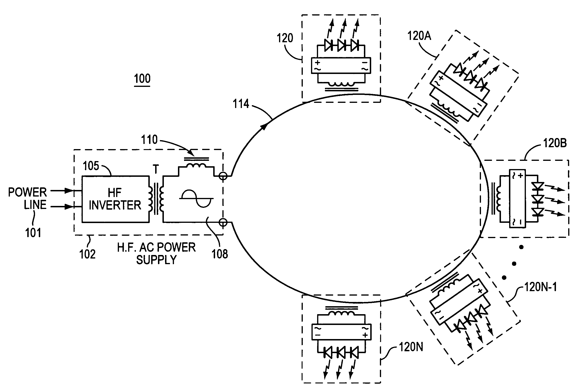
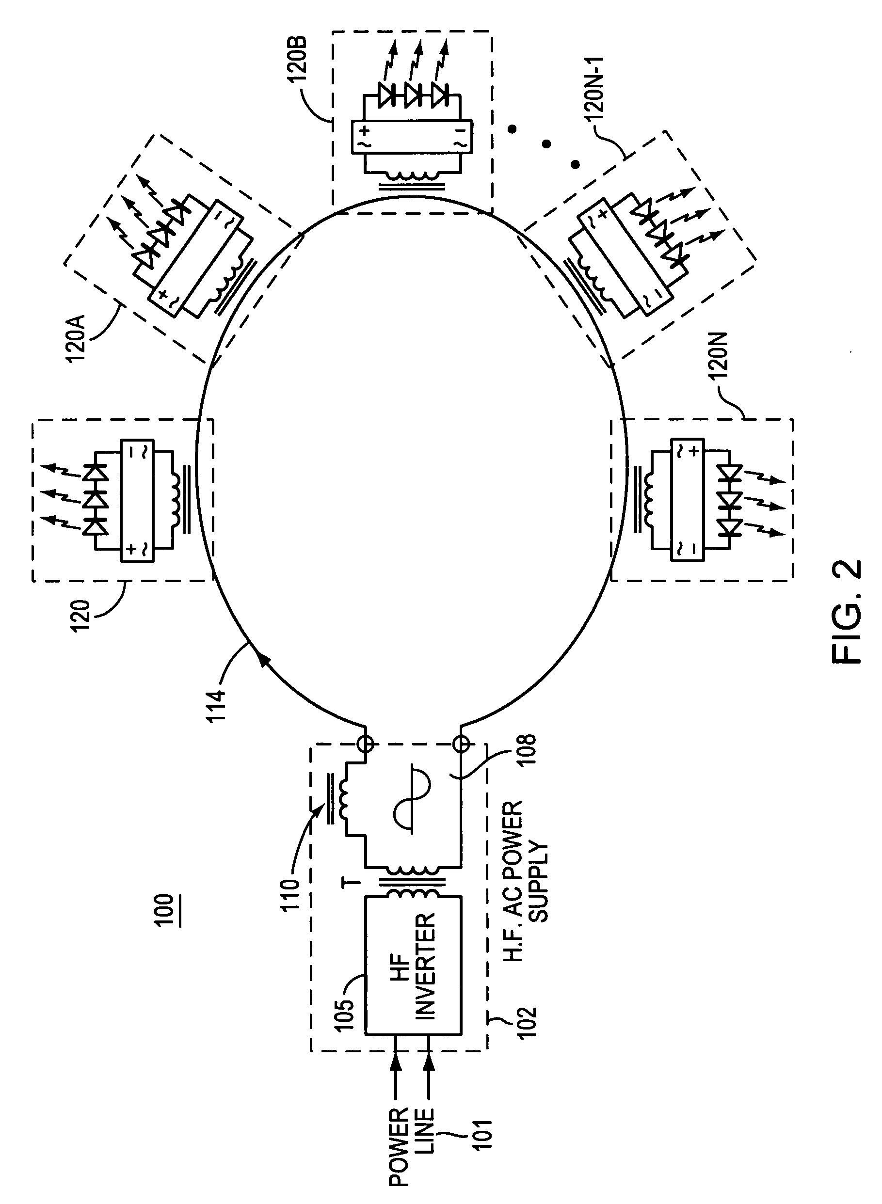
[0042]FIG. 2 illustrates an illumination system 100 suitable for general lighting and illumination of commercial signs. Illumination system 100 includes a high frequency power supply 102 powered by a power line 101 (for example, 110V and 50 Hz or 220 V and 60 Hz). High frequency power supply 102 includes a high frequency (HF) inverter 105 and a current source 108 including a current limiter 110. HF inverter 105 provides a sinusoidal signal of a frequency in the range of 5 kHz to 100 kHz, and preferably in the range of 20 kHz to 40 kHz to transformer T. The output from illumination system 100 is provided to a primary current loop 114. Several illumination modules 120, 120A, 120B . . . 120N are coupled to illumination system 100 using current loop 114. Each illumination module 120 includes an electromagnetic coupling element (shown in detail in FIG. 4B and also shown in FIGS. 2, 2A and 4A) and several light sources that are preferably light emitting diodes (LEDs). In general, the ligh...


PUM


Abstract

An illumination system includes a master power supply providing power to several illumination modules. The master power supply is constructed and arranged to generate high-frequency and low-voltage electrical power provided to a primary wire forming a current loop. Each illumination module includes an electromagnetic coupling element and several light sources. The electromagnetic coupling element includes a magnetic core arranged to receive the current loop in a removable arrangement, and a secondary wire wound around the magnetic core to enable inductive coupling. The secondary wire is connected to provide current to the light sources that may be arranged in the illumination module as a DC load or an AC load.

Description

[0001]This application claims priority from U.S. Provisional Application 60 / 790,627, entitled Illumination Systems, filed on Apr. 10, 2006, which is incorporated by reference.BACKGROUND OF THE INVENTION[0002]The present invention relates to illumination systems and methods, and more particularly, to illumination systems and methods for general lighting and commercial signs.[0003]Commercial lighting systems, used on the outside of commercial buildings for advertising purposes, include channel letters. Channel letters generally include a housing with a concave cross-section about 5″ deep, made of aluminum or plastic. The housing cavity, shaped as the letter, is covered by a translucent plastic sheet of a selected color, illuminated by a light source mounted within. Neon and fluorescent lights provide suitable illumination, allowing the letters to shine brightly when turned on. However, fluorescent light sources have a relatively short life of approximately 20,000 hours. They operate a...

Claims


Application Information

Patent Timeline
IPC IPC(8): H05B39/00H05B44/00F21K99/00
CPCH05B33/0803H02J5/005H05B33/0893H05B33/0815H05B45/58H05B45/395H05B45/355H05B45/39Y02B20/30H02J50/402H02J50/12H02J50/005H02J50/10
Inventor BELAND, ROBERT
Owner EMD TECH
Why Eureka
Try Eureka