Membrane reactor for H2S, CO2 and H2 separation

Active Publication Date: 2007-10-18
GAS TECH INST
View PDF33 Cites 24 Cited by
  • Summary
  • Abstract
  • Description
  • Claims
  • Application Information

AI Technical Summary

Problems solved by technology

However, no single process and system have been identified that are suitable for removal o

Method used


Image

  • Membrane reactor for H2S, CO2 and H2 separation
  • Membrane reactor for H2S, CO2 and H2 separation
  • Membrane reactor for H2S, CO2 and H2 separation

Examples


example

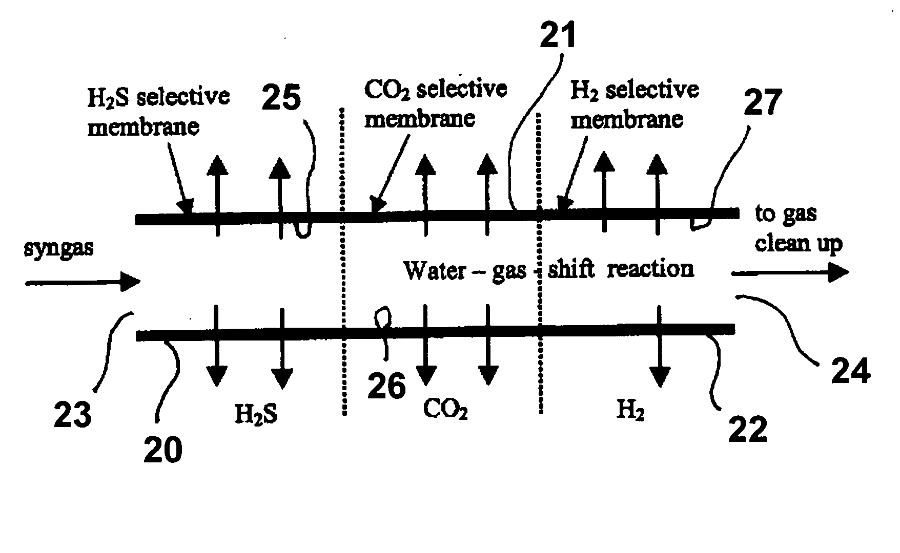
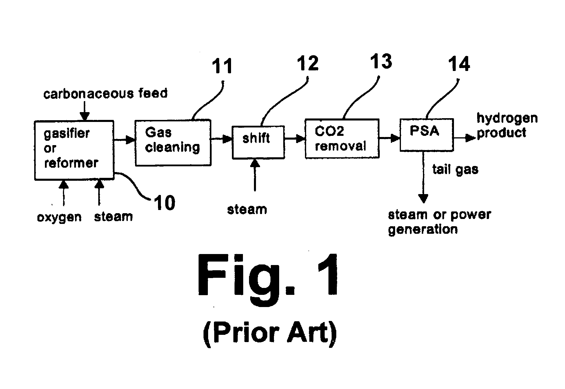
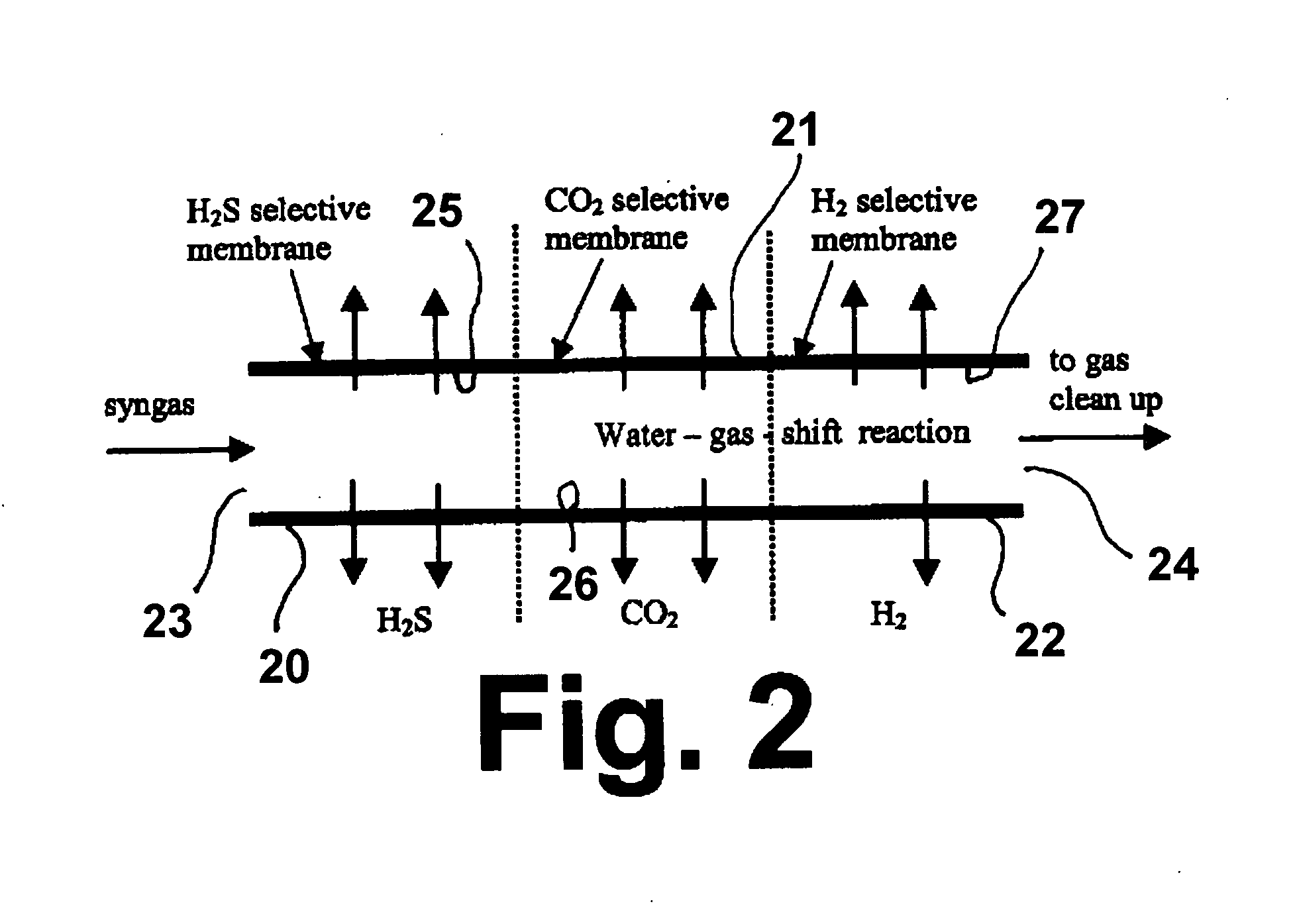
[0027]An Illinois #6 coal is gasified in a gasifier at a rate of about 100,000 lbs / hr, operating at a temperature of about 1000° C. and a pressure of about 30 atm. Steam is provided to the gasifier at a steam / carbon mole ratio of about 0.66 and oxygen is provided to the gasifier at a rate so as to provide an oxygen / carbon mole ratio of about 0.42. Based on the assumptions of thermodynamic equilibrium for all chemical reactions in the system, calculations were performed for four different process schemes: (A) the conventional process without the use of any membrane unit as shown in FIG. 1; (B) the current invention process in which a complementary membrane reactor configuration is employed as shown in FIGS. 2 and 3; (C) the same process as in process (B) but without the use of the H2 membrane in the membrane reactor configuration of FIG. 2; and (D) the same process as the process (B) except without the use of the CO2 membrane in the membrane reactor configuration of FIG. 2. The Ca-ba...


PUM

PropertyMeasurementUnit
Diameteraaaaaaaaaa
Diameteraaaaaaaaaa
Fractionaaaaaaaaaa

Abstract

A system for the selective removal of CO2, H2S, and H2 from a gaseous fluid mixture comprising said CO2, H2S, and H2, which system includes a first membrane section having a nonporous metal oxide membrane, a second membrane section having a CO2-selective membrane, and a third membrane section having an H2-selective membrane. Each membrane section has a feed side and a permeate side and the membrane sections are arranged in series whereby the gaseous fluid mixture contacts the feed side, in sequence, of the first membrane section, the second membrane section and the third membrane section, resulting first in the separation or removal of H2S, second in the separation or removal of CO2, and third in the separation or removal of H2. The process can be used to process synthesis gas generated from the gasification or reforming of carbonaceous materials for hydrogen production and carbon dioxide capture.

Description

BACKGROUND OF THE INVENTION[0001]1. Field of the Invention[0002]This invention relates to a process and system for separation of hydrogen sulfide (H2S), carbon dioxide (CO2), and hydrogen (H2) from a fluid mixture comprising said hydrogen sulfide, carbon dioxide, and hydrogen. More particularly, this invention relates to a membrane reactor process and system that combines hydrogen sulfide removal, water-gas-shift reaction, hydrogen separation and carbon dioxide separation within a single system and, more particularly, within a single membrane configuration. The process and system of this invention is suitable for use in processing synthesis gas generated from gasification and reforming of carbonaceous materials for hydrogen production and carbon dioxide capture. After removal of hydrogen sulfide by the use of a front-end membrane section, the CO conversion of the water-gas-shift reaction from the synthesis gas stream is enhanced by the complementary use of two additional membranes t...

Claims


Application Information

Patent Timeline
IPC IPC(8): B01D53/22
CPCB01D53/228C10J2300/1687B01D71/02B01D71/024B01D2325/08B01J19/2475C01B3/12C01B3/503C01B2203/0244C01B2203/0283C01B2203/0405C01B2203/047C01B2203/0475C01B2203/0485C01B2203/06C01B2203/146C01B2203/86C10J3/82Y02C10/10C10J2300/1643C10K1/004C10K1/005C10K1/32C10K3/04C10J2300/1612B01D69/04Y02C20/40Y02P20/151Y02P30/00
Inventor DOONG, SHAIN-JERJADHAV, RAJA A.LAU, FRANCIS
Owner GAS TECH INST
Why Eureka
Try Eureka